
Understanding Coordinate Reference Systems (CRS): Datum Transformations & EPSG Codes Explained
1. Introduction: Why Coordinate Reference Systems Matter in GIS
Imagine you are creating a GIS map of a river catchment. You import a river network, a digital elevation model (DEM), administrative boundaries, and satellite imagery. Each dataset appears in a different location, and the river no longer follows the valleys visible in the elevation model.Understanding how **Coordinate Reference Systems Datum Transformations EPSG** parameters affect spatial data integration is fundamental to all GIS analysis.
The problem may not be the data themselves. It may be a Coordinate Reference System (CRS) problem.
Every geographic dataset needs a way to describe where its features are located on Earth. A coordinate pair such as 36.8219, -1.2921 has no complete spatial meaning without knowing how those numbers are defined, their order, and the reference system to which they belong.
A CRS provides that framework.
It defines how coordinates relate to locations on Earth, including the reference surface, coordinate axes, units, and, where applicable, the map projection. When datasets have correctly defined coordinate systems, GIS software can usually transform them into a common map display. Problems arise when the CRS is missing, incorrectly assigned, or transformed using an inappropriate operation.
Why GIS students must understand CRS
Coordinate reference systems influence almost every spatial workflow, including:
- Spatial analysis: Ensuring that intersections, buffers, and overlays operate on correctly positioned features.
- Distance and area calculations: Selecting coordinate systems with appropriate measurement units and distortion properties.
- Remote sensing: Aligning satellite imagery with vector boundaries and field observations.
- Surveying and engineering: Maintaining the required positional accuracy for infrastructure and land boundaries.
- Cartography: Choosing a suitable projection for the study area and purpose.
A dataset can look correct at a small scale while containing significant coordinate errors that become apparent when the map is zoomed in or used for precise analysis.
The key principle: Different CRSs do not automatically cause misalignment. QGIS and ArcGIS Pro can transform correctly defined layers on the fly. Misalignment commonly occurs when coordinate metadata is wrong or missing, the wrong datum transformation is used, or coordinates are interpreted in the wrong units or order.
2. Geodesy Basics: Ellipsoids, Geoids, and Datums
To understand coordinate reference systems, you must first understand how geodesists represent Earth’s shape.
Earth is not a perfect sphere. It is slightly flattened at the poles, irregular in its gravitational field, and affected by tectonic motion. GIS therefore uses mathematical and physical reference models to describe positions consistently.
Three foundational concepts are the ellipsoid, the geoid, and the geodetic datum.
2.1 The ellipsoid: A mathematical model of Earth
A reference ellipsoid is a smooth mathematical surface used to approximate Earth’s overall shape. It is defined mainly by its semi-major axis and flattening, or by an equivalent set of parameters.
Because an ellipsoid can be described mathematically, it provides a practical reference surface for calculating latitude, longitude, and height.
Different geodetic systems may use different ellipsoids or different reference-frame definitions.
Common examples include:
- WGS 84 ellipsoid: Associated with the World Geodetic System 1984 and global positioning applications.
- GRS 80 ellipsoid: Used by systems including NAD83.
The two ellipsoids are very similar, but the reference systems associated with them are not automatically interchangeable in high-accuracy work.
2.2 The geoid: A model based on Earth’s gravity field
The geoid is an irregular equipotential surface of Earth’s gravity field that approximates global mean sea level and extends beneath the continents.
Unlike an ellipsoid, which is a mathematical surface, the geoid reflects variations in Earth’s gravity field.
This distinction matters when working with elevation.
A GNSS receiver commonly determines height relative to a reference ellipsoid. Surveyors and engineers often need elevations relative to a vertical datum, such as a national height system.
The relationship can be expressed as:
[
\boxed{h = H + N}
]
Where:
- (h) = ellipsoidal height.
- (H) = orthometric height, commonly described as height above the geoid.
- (N) = geoid undulation, or the separation between the geoid and ellipsoid under the applicable sign convention.
Rearranging the expression gives:
[
\boxed{H = h – N}
]
This is why a GNSS height and a published elevation for the same point may differ. They may refer to different vertical reference surfaces.
NOAA provides a useful explanation of geodetic datums and the geoid in its geodesy reference documentation.
2.3 The datum: Defining the reference framework
A geodetic datum provides the reference framework used to determine coordinates. Depending on the system, it includes an ellipsoid, its positioning and orientation, and a realization through a network of control points or a reference frame.
Modern reference systems may also specify a reference epoch because Earth’s surface changes over time due to tectonic motion, earthquakes, and other processes.
Two datasets can use similar ellipsoids but still report different coordinates for the same physical point because their reference frames differ.
For example, WGS 84 and North American Datum of 1983 (NAD83) were developed for different geodetic purposes. Their realizations, epochs, and relationships to Earth’s changing surface affect the transformation required between them.
2.4 How ellipsoids, datums, and projections fit together
Use this simplified conceptual diagram:
         REAL EARTH
             |
             v
    Reference framework
          (DATUM)
             |
             v
    Mathematical surface
        (ELLIPSOID)
             |
             v
 Geographic coordinates
      Latitude / Longitude
             |
             v
       MAP PROJECTION
             |
             v
   Projected X / Y coordinates
      (e.g. Easting/Northing)
The geoid is a separate physical model associated with gravity and elevation. It is not the surface used by every map projection.
A Coordinate Reference System brings together the necessary definitions for coordinates to be interpreted correctly. A geographic CRS describes positions on the reference surface using angular coordinates. A projected CRS describes positions on a flat coordinate grid using linear coordinates.
3. Geographic vs. Projected CRS in GIS
One of the most important distinctions in GIS is between a Geographic Coordinate Reference System (GCRS) and a Projected Coordinate Reference System (PCRS).
3.1 Geographic Coordinate Reference Systems
A geographic CRS represents locations using angular coordinates, usually latitude and longitude. Many navigation systems default to a simple geographic reference framework based on the **Coordinate Reference Systems Datum Transformations EPSG** criteria for WGS 84.
For example:
Longitude: 36.8219°
Latitude:  -1.2921°
These coordinates identify a location near Nairobi, Kenya, when interpreted in the intended geographic CRS.
Common characteristics include:
- Coordinates are angular rather than linear.
- Units are usually degrees.
- Suitable for global location exchange and many navigation applications.
- Not generally suitable for simple planar distance or area calculations directly from coordinate values.
A longitude difference of 0.01 degrees does not correspond to the same ground distance everywhere. Its east-west ground distance changes with latitude.
3.2 Projected Coordinate Reference Systems
A projected CRS maps locations on a reference surface onto a flat coordinate plane using a mathematical map projection.
Projected coordinates commonly use metres or feet.
An example might look like:
Easting:  700000 m
Northing: 9850000 m
These are illustrative projected coordinates, not a specific location.
Common characteristics include:
- Coordinates are expressed in linear units.
- Distance, area, and spatial analysis can be more convenient.
- Every projection introduces some form of distortion.
- The appropriate system depends on the geographic extent and analytical purpose.
A projected CRS is not automatically accurate for every measurement. Projection distortion varies spatially, so a suitable local or regional CRS must be chosen for the intended analysis.
3.3 Direct comparison
| Feature | Geographic CRS | Projected CRS |
|---|---|---|
| Coordinate values | Latitude and longitude | Easting and northing, often X and Y |
| Common units | Degrees | Metres or feet |
| Surface represented | Reference ellipsoid or sphere | A flat coordinate grid derived through projection |
| Global mapping | Often suitable | Depends on the projection |
| Local distance calculations | Requires appropriate geodesic methods or transformation | Often convenient when using a suitable local projection |
| Area calculations | Requires appropriate geodesic methods or transformation | Often convenient when using an appropriate equal-area or suitable local projection |
| Example | EPSG:4326 | EPSG:32636 |
| Typical use | Data exchange and global positioning | Regional mapping, measurements, and spatial analysis |
4. Understanding EPSG Codes
An EPSG code is a standardized identifier used to identify a coordinate reference system or another geodetic object defined in the EPSG Geodetic Parameter Dataset.
In GIS software, you will commonly search for coordinate systems using identifiers such as EPSG:4326.
The code makes it easier to select a specific CRS without manually entering all of its mathematical parameters.
However, knowing the code does not automatically mean that it is appropriate for your project. You must consider its area of use, units, projection, datum, and intended purpose.
4.1 EPSG:4326 — WGS 84
EPSG:4326 identifies the WGS 84 geographic 2D CRS.
Its primary characteristics are:
- Geographic coordinate system.
- Latitude and longitude expressed in degrees.
- Global area of use.
- Widely used in GPS-related data exchange and mapping.
Example coordinate:
Longitude: 36.8219
Latitude:  -1.2921
In many GIS interfaces and data formats, coordinates are entered or displayed in longitude-latitude order. The formal EPSG definition of EPSG:4326 specifies its axes as latitude followed by longitude, so software interfaces and file formats may handle coordinate order differently.
This axis-order difference can cause errors when coordinates are passed between software libraries, web services, and spatial databases.
See the EPSG:4326 definition for its reference system and coordinate axes.
4.2 EPSG:3857 — WGS 84 / Pseudo-Mercator
EPSG:3857 is commonly used by web-mapping services, including many tile-based basemaps.
Its main characteristics are:
- Projected coordinate system.
- Coordinates expressed in metres.
- Based on the WGS 84 reference system.
- Designed primarily for web mapping and visualization.
Its widespread adoption makes it convenient for displaying web tiles alongside other spatial layers.
However, EPSG:3857 is not a good default for precise area or distance measurement. It uses the Pseudo-Mercator projection, which significantly exaggerates scale toward high latitudes.
For example, Greenland appears much larger relative to Africa on a typical Web Mercator map than it is on the ground. The actual shapes and sizes depend on the map projection being used.
Do not select EPSG:3857 merely because the basemap uses it. Your analysis may require a local projected CRS instead.
More details are available in the EPSG:3857 definition.
4.3 UTM: Universal Transverse Mercator
The Universal Transverse Mercator (UTM) system divides much of the world into 60 zones, each generally 6 degrees of longitude wide. Separate coordinate systems are used for the northern and southern hemispheres.
UTM uses a Transverse Mercator projection to minimize distortion within each zone.
UTM is especially useful for local and regional mapping, including:
- Engineering and surveying.
- Agricultural field analysis.
- Environmental studies.
- Distance and area calculations within an appropriate zone.
A UTM identifier indicates both the zone and hemisphere through the EPSG code.
| CRS | Description | Units |
|---|---|---|
| EPSG:4326 | WGS 84 geographic coordinates | Degrees |
| EPSG:3857 | WGS 84 / Pseudo-Mercator | Metres |
| EPSG:32636 | WGS 84 / UTM zone 36N | Metres |
| EPSG:32736 | WGS 84 / UTM zone 36S | Metres |
The UTM examples are not interchangeable. The correct zone depends on the study area and hemisphere. The EPSG:32636 definition provides an example of a UTM CRS and its area of use.
Practical rule: Use geographic coordinates when you need a global location reference or to exchange data. For local measurements, select a suitable projected CRS for the area and purpose of your analysis.
5. Datum Transformations: Moving Between Geodetic Reference Systems
A datum transformation converts coordinates between different geodetic reference systems.
It differs from a map projection, which converts coordinates from a geographic reference surface to a projected coordinate grid.
This distinction is important because two layers may use projections based on different datums. Changing the map projection alone does not necessarily resolve the underlying reference-frame difference.
5.1 What is a datum transformation?
Imagine a survey dataset created in an older regional datum and a satellite-derived boundary created using WGS 84.
Even if both datasets use latitude and longitude, their coordinates may not identify precisely the same physical positions because they use different reference frameworks.
A datum transformation applies a mathematical operation, sometimes with supporting correction grids, to convert coordinates between the source and destination reference systems.
Conceptually:
Source coordinates
      |
      v
Undo source projection, if needed
      |
      v
Convert between reference frames
 (Helmert / grid / other operation)
      |
      v
Apply destination projection, if needed
      |
      v
Destination coordinates
Not every transformation uses every step in exactly this order. The sequence depends on the source and destination CRSs and the selected coordinate operation.
5.2 WGS 84 vs. NAD83: Why grid shifts matter
WGS 84 is a global reference system used widely in positioning and navigation. NAD83 is a North American geodetic datum developed for regional geodetic control.
Their relationship is more complex than simply assigning a new CRS label.
Different realizations of these reference systems have different relationships to Earth’s physical surface and may use different reference epochs. Consequently, coordinates transformed between them can require a carefully selected operation, especially in surveying, engineering, and other high-accuracy applications.
For some transformations, software may use a Helmert transformation, which describes changes through translations, rotations, scale, and, where relevant, time-dependent parameters.
For others, a grid-based datum transformation is more appropriate.
A grid shift stores spatially varying correction values. The software interpolates between grid nodes to calculate the correction at a particular location.
For example:
Coordinate in source datum
       |
       v
Look up correction in grid
       |
       v
Interpolate horizontal offsets
       |
       v
Apply coordinate shift
       |
       v
Coordinate in destination datum
Grid-based methods can model local variations more effectively than a single uniform shift when suitable grids are available.
The PROJ documentation explains geodetic transformations and horizontal grid shifts.
Important: WGS 84 and NAD83 should not be treated as automatically identical for precision work. The required transformation, its direction, available grid files, and reference epoch all matter. A transformation suitable for one region or datum realization may not be suitable for another.
5.3 On-the-fly transformation
GIS applications can transform coordinates as layers are displayed without changing the original datasets. This is usually called on-the-fly reprojection or on-the-fly coordinate transformation.
For example, you might load:
- A road network in EPSG:4326.
- A terrain raster in a local projected CRS.
- A web basemap in EPSG:3857.
If the CRSs are correctly defined, QGIS or ArcGIS Pro can render these layers in a common project CRS.
The source files remain in their original coordinate systems.
Advantages include:
- Comparing datasets without creating duplicate files.
- Exploring data in a convenient map projection.
- Switching project CRSs during exploratory mapping.
However, on-the-fly transformation does not correct a wrongly assigned CRS or guarantee the best transformation for every precision-sensitive task.
5.4 Permanent reprojection
Permanent reprojection creates a new dataset whose coordinates are stored in a destination CRS. Proper alignment during permanent reprojection hinges on a careful selection of appropriate Coordinate Reference Systems Datum Transformations EPSG operations.
For example, you may transform a GPS point layer from EPSG:4326 to an appropriate local UTM CRS before calculating distances or preparing an engineering dataset.
The source data remain unchanged unless you explicitly overwrite them.
Permanent reprojection is useful when:
- A spatial analysis requires consistent coordinate systems.
- A dataset must be delivered in a specified CRS.
- You need to store measurements in an appropriate linear coordinate system.
- You want a consistent set of projected layers for repeated processing.
Permanent reprojection may involve both a map projection conversion and a datum transformation, depending on the source and destination CRSs.
5.5 Assigning a CRS is not the same as transforming coordinates
This is one of the most important concepts in troubleshooting.
Assigning a CRS tells GIS software how to interpret existing coordinate values. It does not change those values.
Reprojecting a dataset calculates new coordinate values in a different CRS.
For example, suppose a point actually contains longitude and latitude values in WGS 84. Assigning EPSG:4326 identifies the coordinate system but leaves the coordinate values unchanged.
By contrast, transforming the same point to a projected UTM CRS will produce different numeric coordinates, commonly expressed in metres.
A wrong CRS assignment can make an entire layer appear hundreds or thousands of kilometres away from its correct location. Reprojecting the incorrectly labelled layer usually preserves that error because the software starts from the wrong interpretation of the coordinates.
6. Troubleshooting Five Common CRS Errors in QGIS and ArcGIS Pro
CRS problems can be confusing because some errors change only how a layer is displayed, while others alter the coordinate interpretation or produce incorrect analytical results.
The following five cases cover common situations encountered by GIS students.
Error 1: A layer appears in the wrong location
Common cause: The layer has a missing or incorrectly assigned CRS.
For example, a dataset may contain longitude and latitude coordinates but be labelled as a projected CRS. Alternatively, a projected dataset may have lost its .prj file or equivalent spatial reference metadata.
In QGIS
- Right-click the layer and select Properties → Information or inspect its CRS in the layer details.
- Check the coordinate ranges and source metadata.
- Compare the stated CRS with the original data documentation.
- If the CRS is missing or incorrect, use the appropriate Set Layer CRS option to define the correct CRS without changing the coordinates.
- After the CRS is correctly assigned, use Export → Save Features As if you need to create a permanently reprojected copy.
The exact menu location for assigning a CRS can differ across QGIS versions and data sources.
In ArcGIS Pro
- Open the layer’s Properties and inspect its spatial reference.
- Check the source metadata and any associated projection files.
- Use the Define Projection tool only when the coordinates are known to belong to a specific CRS but the spatial reference metadata is missing or incorrect.
- Use the Project tool to create a dataset with coordinates in a different CRS after the source CRS is correctly defined.
Lesson: Do not use the Project tool to repair an unknown or incorrectly assigned source CRS. Determine the correct source system first.
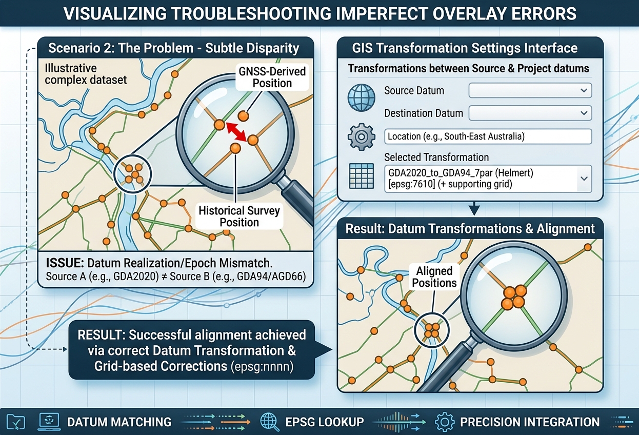
Error 2: Layers overlap imperfectly, even though their CRSs are defined
Common cause: The datasets use different datums or reference-frame realizations, and the appropriate transformation has not been selected.
This may be especially important when combining historic survey data with modern GNSS-derived datasets.
In QGIS
- Open Project → Properties → CRS and review the project CRS.
- Inspect the CRS of the affected layers.
- Open the coordinate-transformation settings in Settings → Options → Transformations when available in your QGIS version.
- Review the available operations between the source and destination datums.
- Select an operation appropriate for your location and accuracy requirements.
- If a transformation requires a grid file, confirm that it is available and supported.
QGIS provides options for controlling coordinate transformations in its configuration documentation.
In ArcGIS Pro
- Open Map Properties → Transformations.
- Review the available geographic transformations between the layer and map CRSs.
- Select the suitable transformation for the study area and required accuracy.
- If needed, configure the geographic transformation environment for processing tools.
See Esri’s coordinate systems and projections documentation.
Lesson: Two correctly labelled layers can still require a specific datum transformation to align at the necessary accuracy.
Error 3: The map looks correct, but distance and area calculations are wrong
Common cause: The measurement method, coordinate units, or projection is inappropriate for the analysis.
For example, a geographic CRS expresses coordinates in degrees. A calculation that treats a degree value as though it were a metre value will produce meaningless results.
Web Mercator also introduces substantial scale distortion, particularly at high latitudes.
How to fix it
- Identify the study area’s extent and the type of measurement required.
- Choose an appropriate projected CRS with linear units for local or regional analysis, or use a suitable geodesic measurement method where appropriate.
- Create a projected copy of the input data when necessary.
- Confirm that the measurement tool uses the expected units and ellipsoid.
- Compare a sample measurement with a trusted reference.
For a small local engineering site, an appropriate local grid projection may be preferable. For a large region or a global study, a suitable equal-area, equidistant, or geodesic method may be more appropriate, depending on the objective.
Lesson: A map that looks correct is not automatically suitable for accurate measurement.
Error 4: A processing operation produces unexpected coordinates or fails
Common cause: The processing tool expects compatible inputs, but one or more layers have inconsistent CRSs, wrong units, or undefined spatial references.
Some algorithms automatically reproject inputs, while others depend on the input CRS, the project CRS, processing settings, or tool-specific environment settings.
In QGIS
- Inspect the input CRS of every layer.
- Read the CRS information displayed in the Processing Toolbox parameters.
- Confirm that the coordinate units make sense for the intended operation.
- Use Warp (Reproject) for raster datasets or an appropriate vector reprojection tool when a common input CRS is required.
- Set the desired output CRS explicitly where the algorithm provides that option.
The QGIS training documentation explains how CRSs are handled during processing.
In ArcGIS Pro
- Inspect each input layer’s spatial reference.
- Review the geoprocessing tool’s output coordinate system, extent, cell size, and other applicable environment settings.
- Use Project for vector data or Project Raster for raster data when a permanent coordinate transformation is required.
- Review transformation settings if the source and destination reference systems differ.
Lesson: Map display settings and geoprocessing settings are related, but they are not necessarily identical.
Error 5: A layer becomes displaced after export or exchange
Common cause: The output CRS was not preserved correctly, the wrong output CRS was selected, a required datum transformation was unavailable, or the destination application interpreted coordinate order or units differently.
This can occur when exchanging data through GeoJSON, CSV, CAD formats, web services, or other systems with different CRS conventions.
How to fix it
- Open the exported file in a new, empty GIS project.
- Check the CRS, coordinate values, units, and metadata recorded in the output.
- Verify the original source CRS and transformation path.
- Confirm the destination application supports the output CRS and any required grid-based transformation.
- Export again with the intended CRS and verify the result independently.
For tabular coordinate data, also confirm whether the fields represent longitude-latitude, latitude-longitude, easting-northing, or another coordinate order.
For high-accuracy applications, document the source CRS, destination CRS, transformation method, and reference epoch when relevant.
Lesson: Always validate an exported dataset in the coordinate system and software environment in which it will be used.
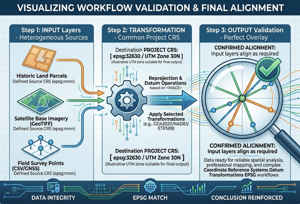
7. A Practical CRS Workflow for Every New GIS Project
The best way to avoid CRS problems is to establish a consistent workflow before you begin analysis.
Step 1: Inspect every input dataset
Record its source, coordinate reference system, coordinate units, and any known accuracy limitations.
Do not assume that every layer uses WGS 84 simply because it was downloaded from the internet.
Step 2: Choose a suitable project CRS
Choose the project CRS according to the study area’s extent and purpose.
For a local project, a suitable UTM zone or national grid may be appropriate. For a global map, a geographic CRS or global projection may be more suitable.
Step 3: Confirm transformations between different datums
Check whether the source and destination CRSs require a datum transformation.
Choose an operation that is appropriate for the location and required accuracy. For precision work, verify the selected transformation’s stated accuracy and any grid-file requirements.
Step 4: Decide whether to transform permanently
For simple visualization, on-the-fly transformation may be sufficient.
For spatial analysis, measurements, editing, or data delivery, determine whether creating a new dataset in a consistent projected CRS will improve reliability and reproducibility.
Step 5: Validate the result
Overlay known control points, reference boundaries, or trusted layers. Check coordinate values, units, and sample measurements.
Save the project with appropriate CRS settings and document any important transformation decisions.
8. Summary Checklist for GIS Students
Before you begin a mapping assignment, confirm the following:
-
Source CRS identified: Every layer has a known and correctly assigned coordinate reference system.
-
Datum understood: You know whether the data use WGS 84, NAD83, a national datum, or another reference system.
-
EPSG code checked: The selected code corresponds to the intended CRS and area of use.
-
Project CRS chosen: Your map uses a CRS suitable for the purpose and geographic extent.
-
Units checked: Degrees are not being mistaken for metres or feet.
-
Transformations reviewed: Datum transformations and grid requirements have been considered where relevant.
-
Analysis CRS selected: Measurement and processing tools use appropriate coordinate systems and methods.
-
Reprojection understood: You know the difference between assigning CRS metadata and changing coordinate values.
-
Output validated: Exported data retain the intended CRS and align with trusted reference layers.
-
Workflow documented: Record the CRS and significant transformation decisions for reproducibility.
9. Conclusion
Coordinate Reference Systems provide the framework that allows geographic data from different sources to be combined meaningfully. Understanding their underlying components—ellipsoids, geoids, datums, coordinate systems, and map projections—helps explain why two layers can contain valid coordinates yet fail to align correctly.
EPSG codes make it easier to identify standard CRSs. Datum transformations allow coordinates to move between different reference systems, while on-the-fly transformation helps GIS applications display heterogeneous layers together. Permanent reprojection, when appropriate, creates new coordinate values for analysis, editing, and data exchange.
For GIS students, the most valuable habit is to investigate the CRS before changing a layer. Confirm what its coordinates actually represent, choose a suitable project system, use appropriate transformations, and verify the results.
These practices provide a strong foundation for more advanced work in surveying, remote sensing, environmental modelling, geospatial databases, and professional GIS analysis. This knowledge provides a critical foundation for all geospatial databases, professional mapping, and complex **Coordinate Reference Systems Datum Transformations EPSG** workflows.
Further Resources
- QGIS: Working with Projections — Layer CRS, project CRS, and coordinate transformation workflows.
- EPSG:4326 — WGS 84 — Geographic coordinate-system definition and axis information.
- EPSG:3857 — WGS 84 / Pseudo-Mercator — Web mapping CRS and its intended use.
- EPSG:32636 — WGS 84 / UTM Zone 36N — Example of a projected UTM coordinate system.
- NOAA: Geodetic Datums and the Geoid — Reference surfaces, datums, and vertical coordinates.
- PROJ: Geodetic Transformations — Transformation methods and grid-based corrections.
- Esri: Coordinate Systems, Map Projections, and Transformations — Practical CRS guidance for ArcGIS Pro.