
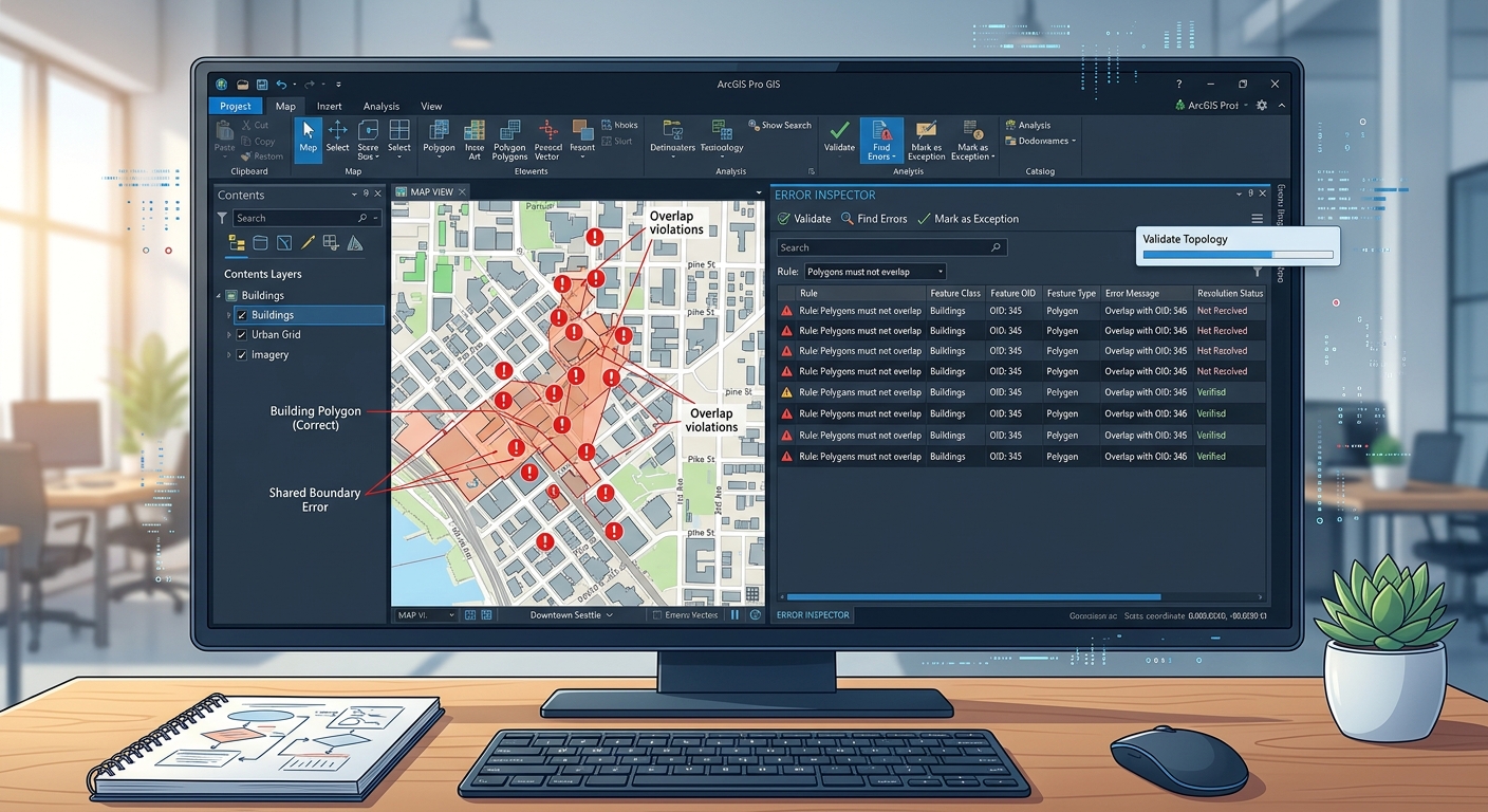
How to Build & Edit Geodatabase Topology Rules in ArcGIS Pro
1. Introduction: Why Geodatabase Topology Matters
When mastering Geodatabase Topology Rules ArcGIS Pro workflows, Imagine digitizing administrative boundaries for a university GIS assignment. You create several adjacent polygons representing wards. One polygon slightly overlaps its neighbour, while another leaves a narrow gap between boundaries.
The map may look correct at a small scale, but these errors can affect area calculations, land-cover statistics, overlay analysis, and other spatial operations.
This is a common GIS data quality problem. The solution is to use geodatabase topology rules in ArcGIS Pro to define which spatial relationships are acceptable and identify features that violate those rules.
Topology describes how spatial features relate to one another. Examples include adjacent polygons sharing boundaries, road segments connecting at junctions, and points falling within administrative areas.
ArcGIS Pro provides geodatabase topology rules that check these relationships, record errors, and support workflows for correcting them. See Esri’s Geodatabase Topology documentation.
Proactive quality control versus reactive correction
There are two ways to manage topology errors.
Reactive correction means digitizing a dataset first and checking for errors only when the work is complete. This can leave hundreds of overlaps, gaps, and incorrectly connected features to fix at the end.
Proactive quality control means creating appropriate topology rules early, using snapping and suitable editing techniques while digitizing, and validating the data regularly.
Topology rules do not necessarily prevent every invalid edit as it happens. Instead, geodatabase topology identifies rule violations during validation. You can make the process more proactive by validating frequently, using appropriate snapping settings, and editing shared boundaries carefully.
This tutorial walks through the full workflow, from creating a file geodatabase to inspecting and fixing topology errors.
2. Prerequisites: Prepare a File Geodatabase and Feature Dataset
Before creating topology rules, organize your GIS data correctly.
A geodatabase topology requires its participating feature classes to reside in the same feature dataset and use the same coordinate system. Geodatabase topology editing and validation require an appropriate ArcGIS Pro license, generally Standard or Advanced. See Esri’s Topology in ArcGIS documentation.
For this tutorial, assume you are preparing administrative boundaries, roads, and land-use polygons.
Step 1: Create a file geodatabase
-
Open ArcGIS Pro and open your project.
-
Open the Catalog pane using View → Catalog Pane, if it is not already visible.
-
In the Catalog pane, right-click Databases, or a suitable project folder, and select New File Geodatabase.
-
Give it a descriptive name, such as
GIS_Quality_Control.gdb. -
Press Enter or click Save, depending on the dialog displayed.
Your file geodatabase is now ready to hold the datasets participating in the topology.
A file geodatabase is a collection of files managed by ArcGIS that stores feature classes, tables, and other GIS datasets. See Create a file geodatabase.
Step 2: Create a feature dataset
A feature dataset groups feature classes that share a coordinate system and may participate in a common topology.
-
In the Catalog pane, expand Databases.
-
Right-click
GIS_Quality_Control.gdb. -
Select New → Feature Dataset.
-
Enter a name such as
Study_Area_Data. -
Select the coordinate system appropriate for your study area.
-
Complete the wizard to create the feature dataset.
Choose the coordinate system based on your intended measurements and analysis. For local area and distance work, an appropriate projected coordinate system is often useful.
Step 3: Import or move your feature classes
If your source layers are shapefiles or feature classes elsewhere in your project, bring copies into the feature dataset.
-
Right-click
Study_Area_Data. -
Use Import → Feature Class(es) or the corresponding import command available in your ArcGIS Pro version.
-
Select the source feature classes, such as
Administrative_Boundaries,Road_Network, andLand_Use. -
Specify valid output names and complete the import.
-
Confirm that the resulting datasets appear beneath
Study_Area_Datain the Catalog pane. -
Verify that the feature classes share the feature dataset’s coordinate system.
If necessary, reproject the source data into the correct coordinate system before importing it. Assigning a coordinate system label is not the same as actually transforming coordinates.
Quality-control tip: Back up your original data before making extensive edits. Topology validation and error repairs can change feature geometry.
3. Step 1: Create a New Topology Dataset
Once the feature dataset is ready, create the topology object that will store the rules and validation results.
Procedure
-
In the Catalog pane, expand your file geodatabase.
-
Locate
Study_Area_Data. -
Right-click the feature dataset and select New → Topology.
-
Follow the topology creation wizard.
-
Provide a descriptive name, such as
Study_Area_Topology. -
Review the cluster tolerance and participating feature classes.
-
Complete the wizard.
Depending on your ArcGIS Pro version and the wizard workflow, some settings are presented during topology creation, while the remaining settings can be adjusted afterward through the topology’s Properties dialog.
Your Catalog pane should now contain a structure similar to this:
GIS_Quality_Control.gdb
└── Study_Area_Data
    ├── Administrative_Boundaries
    ├── Road_Network
    ├── Land_Use
    └── Study_Area_Topology
The topology object defines the validation model for the participating feature classes. It does not replace the original data; it stores the spatial rules and topology-related status information associated with them.
For the official workflow, see Geodatabase topology in ArcGIS Pro.
4. Step 2: Set Feature Classes and Cluster Tolerances
This step is important because topology validation can adjust coordinates that fall within the defined cluster tolerance.
4.1 Add the participating feature classes
-
Right-click
Study_Area_Topologyin the Catalog pane. -
Select Properties.
-
Review the Feature Classes tab, or the corresponding feature-class section in the topology properties.
-
Confirm that each intended feature class participates in the topology.
-
Assign coordinate ranks according to the relative positional accuracy of the datasets, if these settings are available.
A coordinate rank expresses the relative accuracy of the source coordinates. A rank of 1 represents the highest relative accuracy; higher rank numbers represent lower relative accuracy.
For example, if survey-grade administrative boundaries are more accurate than boundaries digitized from a small-scale paper map, the survey-grade data would generally receive the higher rank.
The rank should be based on documented accuracy, not on which layer looks visually better on screen.
4.2 Understand the cluster tolerance
The cluster tolerance is the horizontal distance within which nearby vertices can be treated as coincident during topology processing.
Suppose two boundary vertices are extremely close together. If they fall within the cluster tolerance, topology processing may align them to a common coordinate.
This can help integrate shared boundaries, but it can also move vertices slightly or cause small features to collapse if the tolerance is unsuitable.
-
Open the topology’s Properties dialog.
-
Locate the General tab or the relevant cluster-tolerance setting.
-
Review the existing value and its units.
-
Keep the default tolerance unless you have a documented reason to change it.
-
Confirm that the chosen value is appropriate for the coordinate system and the precision of your source data.
Esri generally recommends the default cluster tolerance in most cases. See Topology properties.
Important: Do not increase the tolerance just to make topology errors disappear. An overly large tolerance can alter geometry and compromise positional accuracy.
5. Step 3: Add Essential Topology Rules
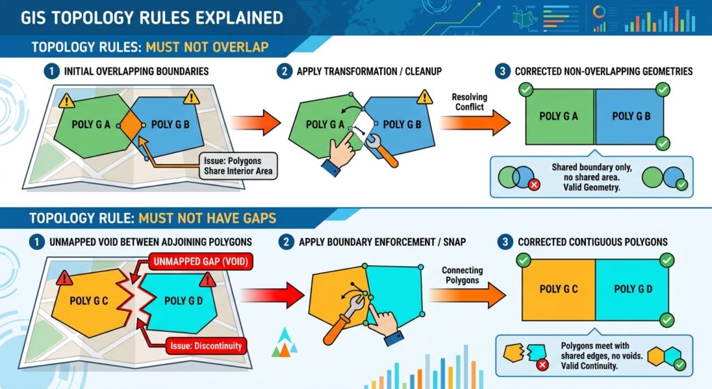
Topology rules define the spatial relationships your dataset must satisfy. For example, a polygon coverage may be required to contain no overlapping polygons, while a road line may be required not to intersect itself.
To manage these rules, open the topology’s Properties → Rules tab.
General procedure for adding a rule
-
In the Catalog pane, right-click
Study_Area_Topology. -
Click Properties.
-
Open the Rules tab.
-
Click the command to add a rule.
-
Choose the relevant feature class or classes.
-
Select the topology rule appropriate for the geometry type.
-
Configure the destination feature class if the rule checks a relationship between two classes.
-
Add the rule and click Apply or OK to save the configuration.
The exact fields depend on the rule selected. Some rules operate within a single feature class, while others compare two different feature classes.
Rule 1: Must Not Overlap
The Must Not Overlap rule is commonly used with polygon datasets such as administrative boundaries, land-use zones, census areas, and parcels.
It checks that polygons within the same feature class or subtype do not overlap one another.
Imagine two adjacent administrative wards. Their shared boundaries should meet, but one ward should not extend into the area occupied by the other.
How to configure it
-
Open Topology Properties → Rules.
-
Add a rule for the relevant polygon feature class, such as
Administrative_Boundaries. -
Select Must Not Overlap.
-
Confirm the rule and save the topology properties.
What happens when an error is found?
ArcGIS Pro identifies the overlapping area as a topology error. Depending on the situation, you may need to move a boundary vertex, reshape a polygon, or remove the unintended overlap.
This rule applies within the specified feature class or subtype. It does not automatically prevent overlaps with polygons in a completely different feature class; that situation may require a cross-class rule such as Must Not Overlap With.
See Esri’s polygon topology rules.
Rule 2: Must Not Have Gaps
The Must Not Have Gaps rule is useful when polygons should form a continuous, gap-free coverage.
Examples include:
- Administrative wards covering an entire county.
- Soil polygons covering a mapped survey area.
- Land-cover polygons intended to represent all mapped land within a defined study boundary.
Consider three adjoining land-use polygons. If their boundaries fail to meet, a small unclassified space may appear between them. The rule identifies such gaps.
How to configure it
-
Open Topology Properties → Rules.
-
Add a rule for the polygon feature class intended to form continuous coverage.
-
Select Must Not Have Gaps.
-
Save the rule.
What happens when an error is found?
ArcGIS Pro identifies gap outlines as topology errors. You may be able to extend a neighbouring polygon, reshape its boundary, or create a new polygon if the gap represents a real feature.
Use this rule carefully. It is inappropriate when gaps are legitimate parts of the dataset, such as intentionally unmapped areas or holes that represent meaningful exclusions. The goal is not to fill every empty space indiscriminately, but to identify gaps that violate the data model.
Rule 3: Must Not Self-Intersect
The Must Not Self-Intersect rule applies to polyline features, not to polygon features.
It checks whether a line crosses or overlaps itself. This can matter for contour lines, survey paths, or line features whose geometry should form a clean path.
For example, a contour line should not unexpectedly cross itself, because the resulting geometry may indicate a digitizing mistake.
How to configure it
-
Open Topology Properties → Rules.
-
Add a rule for the relevant polyline feature class, such as
Road_Networkor a contour dataset. -
Select Must Not Self-Intersect.
-
Save the topology rule.
The rule identifies self-crossings and self-overlaps. However, it does not check every aspect of a road network. If your roads must connect at junctions, additional rules—such as Must Not Have Dangles where appropriate—may be needed.
See Esri’s polyline topology rules.
Quick reference: Selecting the right rule
| Rule | Geometry type | What it checks | Suitable use |
|---|---|---|---|
| Must Not Overlap | Polygon | Overlapping polygons within a class or subtype | Administrative boundaries and mutually exclusive zones |
| Must Not Have Gaps | Polygon | Unintended voids in a continuous polygon coverage | Land-use and soil mapping |
| Must Not Self-Intersect | Polyline | Lines crossing or overlapping themselves | Contours and other line features |
| Must Not Have Dangles | Polyline | Unconnected line ends under the rule’s topology conditions | Connected street or utility networks |
These are common starter rules, not rules that must be applied indiscriminately to every dataset. The correct rules depend on the intended spatial relationships.
6. Step 4: Validate the Topology

Adding rules defines the required relationships, but it does not tell you which existing features violate them. You must validate the topology.
Validation compares the spatial relationships of the participating features against the rules and creates records for detected errors.
Procedure
-
In the Catalog pane, right-click
Study_Area_Topologyand add it to the current map if it is not already present. -
Make sure the relevant feature classes and topology layers are visible in the map.
-
Click the Edit tab on the ArcGIS Pro ribbon.
-
In the Manage Edits group, click Error Inspector.
-
In the Error Inspector toolbar, open the Source drop-down.
-
Select
Study_Area_Topology. -
Click Validate.
The resulting topology errors are displayed in the Error Inspector and symbolized on the map, grouped according to geometry type and topology rule.
Validation extent matters: The Error Inspector’s Validate command can validate the current map extent. To validate the complete topology, use the Validate Topology geoprocessing tool from the Data Management toolbox and select the topology as the input.
You can read more in Esri’s Validate and fix geodatabase topology guide.
What does validation produce?
The Error Inspector may identify:
- Polygon overlaps that violate Must Not Overlap.
- Gap boundaries that violate Must Not Have Gaps.
- Polyline self-intersections that violate Must Not Self-Intersect.
- Other errors associated with the rules you have configured.
Not every topology error is necessarily a mistake. Some may be intentional features of the study design. These should be reviewed and documented rather than automatically removed.
7. Step 5: Inspect and Fix Errors with Error Inspector
After validation, use the Error Inspector to review the errors, decide what each one means, and correct the geometry where necessary.
7.1 Review the error table
-
On the Edit tab, open Error Inspector.
-
Set the Source to your topology.
-
Use the available filters to select particular rules, feature classes, error types, or map extents.
-
Select an error record using the selection box beside its Shape field.
-
Use the available zoom or pan commands to locate the error on the map.
-
Review the Preview and Details tabs to understand the error and its associated features.
Filtering is particularly helpful when a dataset contains hundreds of errors. You can focus on polygon gaps first, repair them, and then move on to overlaps.
7.2 Fix a topology error
Once an error is selected:
-
Open the Fix tab in the Error Inspector.
-
Review the available predefined fixes for that error.
-
Choose a fix only after confirming which feature should be preserved or modified.
-
If no predefined fix is appropriate, use standard editing tools to repair the feature geometry.
-
Save your edits using the Edit tab’s Save Edits command.
Available fixes depend on the error type. For example, an overlap error may offer an option to remove the overlapping portion or merge geometry. A gap error may offer options to create a new feature or merge the affected geometry into an existing feature.
These operations can change your data. Always inspect the geometry and attribute implications before applying a fix.
7.3 When should you mark an error as an exception?
An exception is appropriate when a feature intentionally violates a topology rule and that violation is acceptable under the data specification.
For example, a known design requirement might permit a particular polygon overlap. If the overlap is intentional, you may mark it as an exception so it is not repeatedly reported as an unresolved error.
-
Select the error.
-
Confirm that the violation is intentional and document the reason.
-
In the Fix tab, use Mark as Exception.
-
If the exception is no longer valid, use Clear Exception to reinstate the error.
Do not mark errors as exceptions merely to reduce the number shown in the table. Exceptions should represent justified deviations from the data model, not unfinished corrections.
7.4 Revalidate after editing
-
Run validation again after fixing errors.
-
Inspect any remaining errors or newly created errors.
-
Confirm that the required topology rules are satisfied.
-
Save the edits.
-
Document accepted exceptions and the final validation status.
For extensive or important datasets, repeat the review until the remaining errors are either corrected or documented as legitimate exceptions.
8. Three Rules Every Student Digitizer Should Consider
Before digitizing a new project, think about the data model and choose the topology rules that match it.
1. Must Not Overlap — for polygon coverage
Use this rule when polygons in the same feature class represent mutually exclusive areas, such as wards, parcels, or land-cover zones.
2. Must Not Have Gaps — for continuous polygon coverage
Use this rule when all areas inside a defined coverage are expected to be represented by polygons. Avoid applying it to datasets where empty spaces are legitimate.
3. Must Not Self-Intersect — for suitable polyline datasets
Use this rule when a line should not cross or overlap itself, such as for contour lines or certain survey paths. For road networks, consider additional connectivity rules according to the network design.
These rules establish a useful starting point for polygon and line quality control. They are not a universal checklist for every feature class. Point data, utility networks, parcel fabrics, and transport datasets may need different rules.
9. Practical Quality-Control Checklist
Before submitting a university GIS assignment or handing a dataset to another analyst, use this final checklist.
-
The file geodatabase and feature dataset have descriptive names.
-
All topology participants are in the same feature dataset and use the same coordinate system.
-
The cluster tolerance has been reviewed and is appropriate for the source data.
-
Rules reflect the intended relationships between the features.
-
The topology has been validated over the intended study area.
-
Errors have been inspected and corrected where necessary.
-
Intentional exceptions have a documented reason.
-
The topology has been revalidated after the final edits.
-
Edits have been saved, and the original data can be restored if needed.
10. Conclusion
Geodatabase topology is one of the most useful quality-control tools available in ArcGIS Pro. It allows GIS practitioners to define acceptable spatial relationships, detect inconsistent geometries, and manage errors before they undermine subsequent analysis.
The workflow is straightforward: prepare a file geodatabase and feature dataset, create a topology, configure feature classes and cluster tolerance, add suitable rules, validate the topology, and inspect and repair detected errors.
The most important principle is to choose rules based on the meaning of your data. A gap may be an error in a continuous land-cover map but a legitimate feature in another dataset. A line intersection may be acceptable for a road network but not for a contour line.
Good GIS data quality is not simply about eliminating every flagged error. It is about ensuring that the geometry accurately represents the real world and follows a clearly defined data model.