
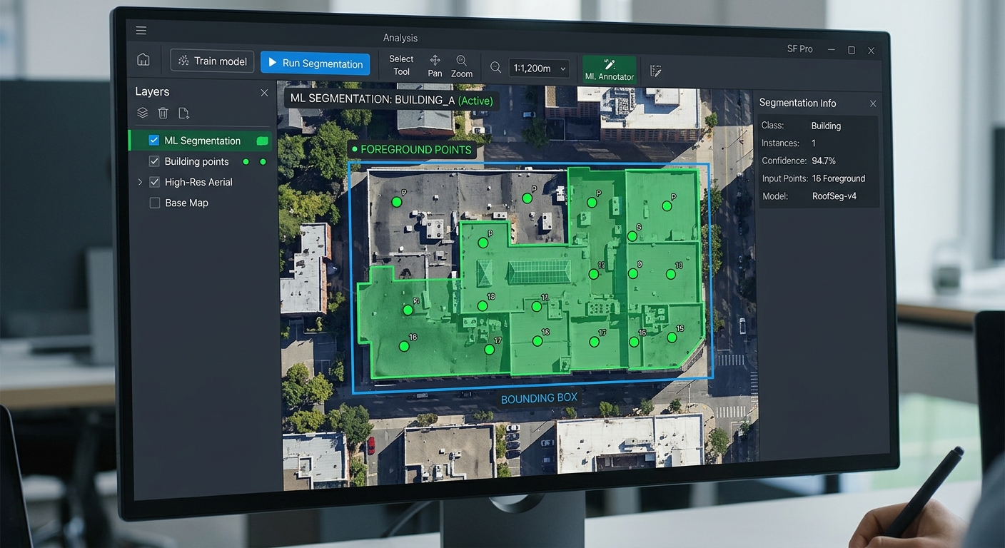
Segment Anything Model (SAM) for Automated Building Extraction in QGIS
Introduction
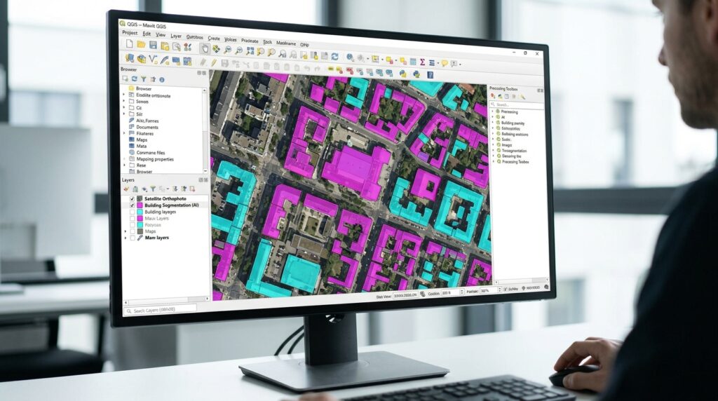
Using the Segment Anything Model SAM QGIS building extraction workflow significantly streamlines automated feature digitizing and spatial analysis compared to manual vector tracing. Building footprint extraction is one of the most time-consuming tasks in remote sensing and GIS. In conventional workflows, an analyst examines aerial imagery, traces building boundaries manually, edits vertices, and saves the resulting polygons into a vector layer. For a large urban area containing thousands of buildings, this process can require substantial time and repetitive editing.
Meta’s Segment Anything Model (SAM) introduces a different workflow. Rather than tracing every boundary manually, an analyst provides prompts—such as foreground points, background points, or bounding boxes—and the model predicts image masks corresponding to the selected objects.
In QGIS, this creates a practical GeoAI workflow for AI satellite image segmentation and automated feature digitizing. The output can be converted into vector polygons and refined using conventional GIS processing tools.
Two relevant plugins are available through the QGIS ecosystem:
-
SamGeo supports interactive point prompts, bounding-box prompts, text-based segmentation in supported model versions, and raster or vector outputs.
-
Geo SAM provides model management and supports multiple SAM model families, including SAM, SAM 2, SAM 2.1, and SAM 3.
This tutorial uses SamGeo for the primary workflow because its documented interface includes point prompting, box prompting, model selection, and output export.
The objective is to extract building footprints from a high-resolution orthophoto, convert the segmentation masks into editable polygons, and clean the resulting vector layer.
Important: SAM is a general-purpose segmentation model, not a guarantee of building detection. It can identify plausible image objects without knowing that they are buildings. Roofs, paved areas, shadows, pools, and vegetation may therefore be segmented incorrectly. Human validation remains essential.
1. Prerequisites and Setup
1.1 Required software and data
Before beginning, prepare the following:
| Requirement | Purpose |
|---|---|
| QGIS 3.22 or later | Loads imagery and manages the GIS processing workflow; verify compatibility with your chosen plugin release. |
| High-resolution GeoTIFF or orthophoto | Input for building segmentation. |
| SamGeo or Geo SAM plugin | Provides the SAM interface inside QGIS. |
| Compatible Python and PyTorch environment | Runs the model and its dependencies. |
| SAM model weights | Supplies the trained model parameters. |
| GPU or CPU | Runs segmentation inference. |
| GeoPackage output | Stores editable building polygons and their attributes. |
The SamGeo plugin documentation specifies QGIS 3.22 or later and Python 3.10 or later for its current documented setup. Its model and dependency requirements vary with the SAM version selected.
Recommended image characteristics
For building extraction, use orthorectified, high-resolution imagery with clearly visible roof boundaries.
Suitable sources include aerial orthophotos, UAV orthomosaics, and high-resolution commercial or government satellite imagery.
The appropriate resolution depends on the size of the buildings. Images at sub-meter resolution are generally more useful for individual roof boundaries than medium-resolution satellite imagery, but image quality, viewing angle, shadows, and roof contrast all influence segmentation quality.
A 10 m Sentinel-2 image, for example, is generally unsuitable for reliably delineating individual small buildings because many roofs occupy only a few pixels.
1.2 Install the QGIS plugin
Open QGIS and follow these steps:
-
Go to Plugins → Manage and Install Plugins.
-
Select the All tab.
-
Search for
SamGeo. -
Select the compatible release and click Install Plugin.
-
Restart QGIS if requested.
-
Look for the SamGeo toolbar icon or open Raster → SamGeo → SamGeo Segmentation.
The repository documents these plugin access paths.
You can also install Geo SAM through the same Plugin Manager by searching for Geo SAM. Its official QGIS plugin listing documents in-plugin model management and dependency support.
Choose your plugin version carefully
SamGeo’s QGIS repository currently lists stable and experimental releases separately. At the time of writing, the listed stable release is 1.2.0 and the experimental release is 1.4.0. If a particular model or text-prompt control is missing, check the release notes before assuming the installation has failed.
1.3 Configure the Python environment
Installing the QGIS plugin does not always mean that every deep-learning dependency is installed in the Python environment running QGIS.
If the plugin opens correctly and can load its models, you can proceed to the next section. If it reports a missing samgeo, torch, or related module, use the setup instructions for your plugin release and operating system.
The SamGeo maintainers document a Conda-based environment for installing QGIS and the geospatial SAM package. On macOS or Linux, their documented starting point is:
# Create an isolated Python environment
conda create -n geo python=3.12

# Activate the environment
conda activate geo

# Install QGIS and the base geospatial SAM package
conda install -c conda-forge qgis segment-geospatial

# Install the additional dependencies for SAM 3 support
pip install -U "segment-geospatial[samgeo3]"
The final command installs optional dependencies for SAM 3. You do not necessarily need the SAM 3 extras to run an older supported model. Consult the SamGeo plugin documentation for the installation instructions matching your version.
Windows users: Deep-learning dependencies can be particularly sensitive to mismatched Python, PyTorch, CUDA, and QGIS environments. The plugin maintainers publish Windows-specific instructions for their supported SAM 3 setup. Avoid installing packages into an arbitrary system Python and assuming QGIS will automatically use them.
2. Configure CUDA, CPU, and Model Weights
SAM inference can run on a CPU, but a compatible GPU can substantially reduce the time required for large imagery and repeated interactive prompts.
2.1 CUDA GPU configuration
For an NVIDIA GPU, the requirements include a compatible PyTorch build and functioning CUDA support.
The practical setup process is:
-
Confirm that the GPU and NVIDIA driver are supported by your chosen PyTorch installation.
-
Install PyTorch with a compatible CUDA build in the environment used by QGIS.
-
Restart QGIS using that environment.
-
Open the SamGeo panel.
-
In the Model tab, choose the model version.
-
Set the device to
cudaorauto. -
Click Load Model.
The SamGeo interface documents auto, cuda, and cpu device selection.
You can also inspect CUDA availability from the Python environment that runs QGIS:
# Run this in the QGIS Python Console if torch is installed.import torchprint("PyTorch version:", torch.__version__)print("CUDA available:", torch.cuda.is_available())if torch.cuda.is_available(): print("GPU:", torch.cuda.get_device_name(0))If torch.cuda.is_available() returns False, choosing cuda in the plugin will not make the GPU available. Resolve the environment or driver issue, or switch to CPU.
2.2 CPU configuration
If you do not have a compatible NVIDIA GPU:
-
Open the SamGeo panel.
-
Select the desired SAM model.
-
Choose
cpuas the device. -
Load the model.
-
Test it on a small image subset before processing a larger study area.
CPU inference is often adequate for learning the workflow or segmenting selected buildings, although repeated interactive prompts can be slower.
For large scenes, crop the imagery to a manageable area, avoid unnecessarily large input images, and use batch processing only after testing representative objects.
2.3 Obtain compatible model weights
SAM models use version-specific weights. A checkpoint for the original SAM model should not be assumed to work with SAM 2 or SAM 3.
For the original SAM implementation, Meta provides several model sizes:
| Model | Checkpoint filename |
|---|---|
| ViT-B | sam_vit_b_01ec64.pth |
| ViT-L | sam_vit_l_0b3195.pth |
| ViT-H | sam_vit_h_4b8939.pth |
These are the official checkpoint filenames for the original SAM model.
Use the plugin’s model manager or its documented download mechanism whenever available. This reduces the chance of choosing a checkpoint incompatible with the selected model family.
SAM 3 note: SamGeo documents that SAM 3 setup requires Hugging Face authentication and access to the model. You may need to sign in and request access before the plugin can download or load it.
For this building-extraction workflow, SAM 1 or SAM 2 with point and box prompts may be sufficient. Text prompting is an additional option in supported model versions, not a requirement for extracting buildings.
3. Load High-Resolution Imagery into QGIS
Step 1: Add the orthophoto or satellite image
In QGIS:
-
Select Layer → Add Layer → Add Raster Layer.
-
Browse to the GeoTIFF or orthophoto.
-
Click Add.
-
Zoom to the raster layer.
-
Inspect the image to confirm that individual roofs are visible.
Check the raster properties by right-clicking the image layer and selecting Properties.
Under the Information section, inspect:
-
Coordinate reference system (CRS).
-
Raster width and height.
-
Number of bands.
-
Pixel size.
-
Data type and NoData information.
SAM operates on image pixels, so the visible image detail is central to segmentation quality. Keep the raster’s geographic reference intact for spatial outputs.
Step 2: Prepare a manageable processing area
Do not start by passing a very large regional mosaic into an interactive segmentation workflow.
Instead:
-
Identify a representative block or neighborhood.
-
Open the Processing Toolbox.
-
Search for Clip Raster by Extent or Clip Raster by Mask Layer.
-
Select the input imagery.
-
Set the target extent or study-area polygon.
-
Save the result as a new GeoTIFF.
A cropped raster is useful for three reasons:
-
It reduces the amount of imagery being processed.
-
It allows you to inspect the result at a practical map scale.
-
It makes model failures easier to diagnose.
For a large city, divide the project into manageable blocks and keep a record of each processed extent.
Recommended practice
For an initial test, choose an area that contains different roof types, building sizes, roof colors, and some difficult cases such as tree shadows or buildings close to roads.
A small but varied test area is more useful for evaluating the model than choosing only the clearest roofs.
4. Initialize the SAM Model on the Input Raster
Step 3: Open the SamGeo segmentation panel
Use the SamGeo toolbar icon or navigate to:
Raster → SamGeo → SamGeo Segmentation
The panel is documented as having tabs for model selection, text prompts, interactive prompts, batch work, and output. Exact labels can vary between releases.
Step 4: Select and initialize the model
In the Model tab:
-
Select the SAM model version.
-
Select the backend, where available.
-
Set the device to
auto,cuda, orcpu. -
Set the confidence threshold if the selected model supports it.
-
Enable interactive mode for point and box prompts.
-
Click Load Model.
Allow the model to finish initializing before attempting segmentation.
The model may download weights or perform initial preprocessing the first time it loads. Later runs may reuse the downloaded weights and cached model files.
Step 5: Assign the input image
The SamGeo interface supports selecting a raster layer from the layer dropdown and clic
Select the cropped orthophoto created in Step 2.
After assigning the image, inspect the map and confirm that the input matches the scene you intend to segment. Do not assume the plugin automatically crops the image to the current QGIS map-canvas extent; use a dedicated subset when you need precise control over processing boundaries.
5. Segment Individual Buildings with Prompts
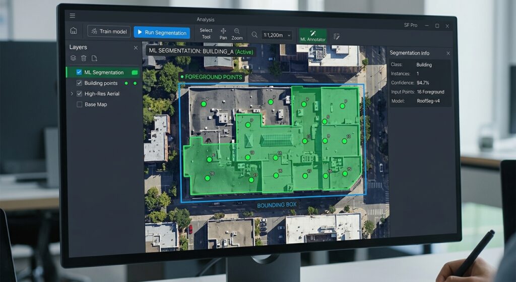
Prompt-based segmentation is where the main advantage of SAM becomes apparent. Instead of tracing every roof boundary vertex by vertex, you indicate the object of interest and let the model infer a mask.
There are two primary workflows: point prompts and bounding-box prompts.
Step 6: Use foreground and background points
Open the plugin’s Interactive tab.
Follow this sequence:
-
Select Add Foreground Points.
-
Click inside the roof you want to extract.
-
Add further foreground points if the roof has several visually distinct sections.
-
Select Add Background Points.
-
Click outside the building on a road, tree, shadow, or nearby roof that should not be included.
-
Click Segment by Points.
-
Inspect the predicted mask.
-
Add or reposition prompts if necessary, then run the segmentation again.
The plugin documentation confirms that positive and negative point prompts can be used in the interactive workflow.
Prompting strategy for buildings
Foreground
Place the point on the roof.
Avoid placing it on a roof shadow, adjacent tree, or background pavement. For a large roof with multiple wings, try more than one positive point.
Background
Place a negative point outside the intended building.
Use it near a boundary that the mask has mistakenly crossed, such as a roof beside a paved parking area.
When point prompts work best
Points are particularly effective when the building is visually distinct but irregular in shape, or where one roof touches a neighboring object and requires more precise guidance.
For example, a large industrial roof may need positive points in different sections, while a negative point near a row of trees may help the model exclude surrounding vegetation.
Step 7: Use a bounding box
For a clearly identifiable building, a box can be faster than multiple points.
In the Interactive tab:
-
Click Draw Box.
-
Draw a rectangle around the building.
-
Include the full roof footprint while avoiding unrelated structures.
-
Click Segment by Box.
-
Inspect the predicted result.
-
Adjust the box or switch to point prompts if necessary.
SamGeo documents this exact box-based workflow.
Bounding boxes are useful for buildings with a clear separation from their surroundings. They can be less reliable where multiple connected roofs, dense tree canopies, or strong shadows create ambiguous boundaries.
Step 8: Segment additional feature types
The same prompting workflow can be applied to other objects, although the results must be inspected carefully.
| Feature | Recommended approach | Common difficulty |
|---|---|---|
| Buildings | Positive point or tight bounding box | Shadows and adjacent roofs |
| Swimming pools | Positive point within the pool | Similar-colored roofs or water surfaces |
| Solar panels | Tight box plus positive point | Small panels can blend into roof texture |
| Forest patches | Positive points in vegetation and negative points outside | Mixed canopy boundaries and shadows |
| Roadside structures | Box or multiple points | Buildings touching paved surfaces |
SAM’s task is to identify image objects and boundaries, not to guarantee the correct semantic class. A mask around a rectangular parking lot may look convincing while still being a false building detection.
Step 9: Try text prompts where supported
Some current SamGeo model versions include text-based segmentation. In the Text tab, enter a prompt such as:
buildingThen click Segment by Text.
Other possible prompts include tree, road, or water, depending on the model and the visual characteristics of the imagery.
The plugin documentation identifies text-based segmentation as a feature of its supported SAM versions, particularly the SamGeo3/SAM 3 workflow.
Do not assume text prompts will work in every SAM release or backend. If your selected model lacks text prompting, use point or box prompts instead.
6. Run Batch Segmentation for Many Buildings
Interactive prompts are useful for isolated objects, but city-scale building extraction requires a more systematic approach.
One option is to prepare a point layer containing approximate building centroids. These could be generated from existing building records, manually placed seeds, or another detection process.
In the SamGeo Batch tab:
-
Select the point vector layer or browse to a point file.
-
Specify its CRS if the plugin cannot determine it automatically.
-
Configure minimum or maximum object size filters if supported.
-
Choose an output raster path if required.
-
Click Run Batch Segmentation.
The plugin documentation states that batch point segmentation uses each input point to generate a separate mask.
This can accelerate extraction in areas where approximate building locations are already known.
However, batch prompts are not equivalent to unrestricted automatic building detection. If a point falls on a tree, road, courtyard, or adjacent building, the resulting mask may be wrong.
For a large region without seed points, consider generating candidate building locations with a building detector or another model first, then use SAM to refine the proposed boundaries.
7. Save Segmentation Results as Raster or Vector Data
After inspecting the masks, the next step is exporting them to a persistent GIS dataset.
Step 10: Save the mask
Open the plugin’s Output tab.
-
Choose the output format.
-
Select raster or vector output.
-
Specify the output path.
-
Click Save Masks.
The SamGeo interface documents export to raster or vector formats.
For a new project, a GeoPackage is a practical vector target because it can store polygons and attributes in a single file, handles complex geometries better than the Shapefile format, and is convenient for subsequent QGIS editing.
Use a descriptive filename, such as:
building_masks_raw.gpkgIf you save a GeoTIFF mask, use a name such as:
building_mask.tifThe raster route is useful when you need to inspect the binary mask, preserve intermediate outputs, or run additional raster-based filtering before vectorization.
8. Convert Raster Masks into Editable Building Polygons
If the plugin exported a vector layer directly, skip to Step 12.
If it exported a raster mask, use QGIS’s polygonization tools to convert mask regions into polygons.
Step 11: Polygonize the raster mask
Open the Processing Toolbox and search for:
Polygonize (Raster to Vector)
This is the GDAL polygonization workflow. Polygonization creates polygons representing connected regions of pixels with the same raster value.
Configure the tool:
-
Select
building_mask.tifas the input raster. -
Select the correct raster band.
-
Choose a field to receive the raster value, usually
DN. -
Specify a GeoPackage output.
-
Run the algorithm.
The resulting polygon layer may contain both background and object regions, depending on how the mask is encoded.
Handle background values correctly
For a binary mask:
-
0commonly represents background. -
A nonzero value represents the segmented area.
Do not assume every polygon produced by polygonization is a building. Inspect the DN values in the attribute table, select the object class, and exclude the background.
Where the tool allows a valid-data mask, you can configure it to process only the intended object pixels. Alternatively, use a raster calculator or another raster preprocessing step to represent background pixels as NoData before polygonization.
Save the filtered output as:
building_footprints_initial.gpkgWhy polygonization matters
A binary raster mask contains pixel-based shapes. Polygonization converts the boundaries of connected mask regions into vector geometries that can be edited, queried, measured, styled, and stored in a spatial database.
It does not automatically improve accuracy or remove false positives; those steps come next.
9. Clean and Validate the Vector Building Footprints
The first SAM output should be treated as a draft segmentation layer rather than a final building inventory.
False positives, touching roofs, holes, small fragments, and irregular pixel edges are common.
Step 12: Fix invalid geometries
In the Processing Toolbox, search for:
Fix Geometries
Run it on building_footprints_initial and save the result as:
building_footprints_fixed.gpkgThis helps correct invalid geometries produced during mask conversion and subsequent processing.
Step 13: Separate multipart features
Search for:
Multipart to Singleparts
Run the algorithm if features contain several disconnected polygons grouped in one multipart geometry.
This is useful when you need a separate feature for each building footprint.
Be careful: adjacent buildings may be merged into one connected mask. Separating multipart features will not automatically split two buildings that have already been joined into one polygon.
Step 14: Remove small false positives
SAM may identify small objects that resemble roofs, such as sheds, vehicles, rooftop equipment, or bright concrete surfaces.
First, reproject the layer into an appropriate projected CRS for your study region so that the geometry measurements are in meaningful linear units.
Then use Extract by Expression or Select by Expression to filter features by area.
For example, where the projected CRS uses meters, you might test:
$area >= 12This selects polygons with an area of at least 12 square meters, subject to the project’s ellipsoid and measurement settings.
Do not use 12 m² as a universal building threshold. Choose a minimum area based on your smallest legitimate structure, image resolution, and intended mapping scale. Small homes, kiosks, and outbuildings may be valid objects.
If the smallest meaningful structure is 8 m², a 12 m² threshold would remove valid buildings.
A good practice is to add an area field and inspect its distribution before deciding on the threshold.
Step 15: Simplify overly complex boundaries
Pixel-derived polygons often contain many small vertices along roof edges. Simplification can reduce these vertices and make the dataset more manageable.
In QGIS:
-
Open the Processing Toolbox.
-
Search for Simplify geometries.
-
Select the cleaned building layer.
-
Choose a simplification method.
-
Set a tolerance appropriate to the imagery resolution.
-
Save the result as a new layer.
QGIS supports distance-based simplification and alternative methods; its documentation explains that the tolerance controls how aggressively vertices are removed.
For building footprints, use a conservative tolerance. Excessive simplification can remove narrow roof extensions or distort small buildings.
Step 16: Smooth only where appropriate
QGIS also provides Smooth under the vector geometry tools.
Smoothing adds vertices and rounds corners, potentially improving irregular boundaries but also changing geometry.
For building extraction, apply smoothing selectively rather than automatically to every polygon.
Most buildings have straight, angular roof edges. Aggressive smoothing may therefore make a footprint less accurate, not more accurate.
For many urban building layers, gentle simplification followed by manual vertex correction is preferable to heavy smoothing.
Step 17: Inspect and correct false positives
Create a comparison view with:
-
The original imagery.
-
The raw mask or initial footprint layer.
-
The cleaned footprint layer.
Use transparent polygon fills and contrasting outlines so roof edges remain visible.
Inspect the following cases carefully:
-
Buildings under tree canopy.
-
Adjacent buildings touching along their roofs.
-
Roofs partly hidden by shadows.
-
Large paved surfaces incorrectly segmented as roofs.
-
Bright vehicles or structures mistaken for small buildings.
-
Roof areas split into several fragments.
-
Several individual buildings combined into one polygon.
Use QGIS’s editing tools to split, merge, reshape, or delete features where necessary.
The final layer should be based on visual verification, not merely on the absence of processing errors.
10. Calculate Building Attributes and Save the Final Dataset
A useful building inventory should contain more than geometry.
Open the attribute table of your cleaned footprint layer and use the Field Calculator to add fields such as:
| Field | Example type | Purpose |
|---|---|---|
building_id |
Integer or text | Unique building identifier |
area_m2 |
Decimal | Building footprint area |
perimeter_m |
Decimal | Polygon perimeter |
review_status |
Text | Manual verification status |
source_method |
Text | Segmentation method |
confidence |
Decimal, if available | Confidence value from the actual output model, if provided |
For a projected CRS in meters, use the following expressions where appropriate:
Footprint area:
$areaPerimeter:
$perimeterCheck your project’s ellipsoid settings and geometry units before interpreting the result as square meters or meters.
Finally, export the cleaned layer to a persistent GeoPackage:
Right-click layer → Export → Save Features As…
Choose:
-
Format: GeoPackage
-
File:
building_footprints_final.gpkg -
Layer name:
building_footprints -
CRS: the selected project or analysis CRS
Ensure the output includes the desired attributes, then load it back into QGIS and verify the result.
11. Optional: Automate the Workflow with the QGIS Python Console
The graphical workflow is suitable for learning and processing selected areas. Once the workflow is stable, you can automate parts of the vector cleanup using the QGIS Processing framework.
For example, the following script repairs the geometries and simplifies the resulting layer:
import processing# Replace this path with the vector layer produced by SAM.input_layer = "/path/to/building_footprints_initial.gpkg"# Output pathsfixed_output = "/path/to/building_footprints_fixed.gpkg"simplified_output = "/path/to/building_footprints_simplified.gpkg"# Step 1: Repair invalid polygon geometries.processing.run( "native:fixgeometries", { "INPUT": input_layer, "OUTPUT": fixed_output })# Step 2: Simplify geometries using a conservative tolerance.# Choose a tolerance in the units of the layer CRS.processing.run( "native:simplifygeometries", { "INPUT": fixed_output, "METHOD": 0, "TOLERANCE": 0.15, "OUTPUT": simplified_output })print("Vector cleanup completed.")Important script notes
This script assumes that the input is a vector layer and that the layer CRS uses meters. The 0.15 tolerance is only an example; it should be adjusted according to the orthophoto’s resolution and the size of the smallest building.
Automating geometry repair and simplification does not eliminate the need to review the extracted footprints. It simply makes the repeatable cleanup stages easier to execute.
You can expand this processing script to include multipart separation, attribute creation, area filtering, and export. The model inference itself should follow the API of the SamGeo or Geo SAM version installed in your QGIS environment.
12. Manual Digitizing vs SAM-Assisted Extraction
SAM changes the interaction between the analyst and the image, but it does not remove all mapping work.
| Criterion | Manual tracing | SAM-assisted extraction |
|---|---|---|
| Initial operation | Digitize vertices around each building | Supply prompts and generate a mask |
| Throughput | Decreases as the building count grows | Can be faster for repeated, clearly visible objects |
| Boundary quality | Depends on analyst skill and zoom level | Depends on image quality, model behavior, and prompt placement |
| Complex roofs | Requires careful vertex placement | May follow irregular boundaries, but can confuse touching objects |
| False positives | Less dependent on model behavior, but human mistakes remain possible | Requires review of roads, shadows, vegetation, and other similar surfaces |
| Batch processing | Usually repetitive unless other automation is used | Supports batch workflows where seeds or supported prompts are available |
| Final editing | Required for digitizing errors | Still required for segmentation errors |
SAM can reduce the amount of manual tracing needed, particularly when buildings have visible boundaries and the model produces useful masks from a small number of prompts.
However, time savings and boundary precision are dataset-dependent. Do not claim that SAM will always be faster or more accurate than manual tracing without evaluating the actual imagery and workflow.
12.1 How to evaluate accuracy objectively
Select a representative sample of buildings and create carefully reviewed reference footprints.
Then compare the SAM-derived polygons against the reference data.
One useful measure is Intersection over Union (IoU):
where:
-
\(A\) is the area of the predicted footprint.
-
\(R\) is the area of the reference footprint.
-
\(A \cap R\) is their intersection.
-
\(A \cup R\) is their union.
An IoU closer to 1 indicates greater spatial overlap between a predicted footprint and the reference footprint.
For a fair comparison, record the time required to process the same test area using manual tracing and SAM-assisted extraction, including the time spent correcting errors. Also compare missed buildings, false detections, and boundary alignment.
This gives you a defensible estimate of time efficiency and accuracy for your own geographic area instead of relying on general claims about AI performance.
13. Troubleshooting Common Problems
The model fails to load
Check that the required Python package is installed in the environment used by QGIS, verify that the selected model has compatible weights, and make sure sufficient memory is available.
If CUDA fails, try a CPU test to distinguish a model or image problem from a GPU configuration problem. The SamGeo documentation recommends checking dependencies, GPU memory, and restarting QGIS when model loading fails.
Segmentation is slow
Start with a smaller raster subset. If an NVIDIA GPU is available, confirm that the CUDA-enabled PyTorch build is working and that the plugin is actually using the GPU.
The SamGeo documentation also recommends reducing image resolution where appropriate and testing a different backend where supported.
The mask includes an entire road or neighboring roof
Try a tighter box and add background points near the incorrect boundary.
If the objects have almost identical visual characteristics or are touching, the model may not have enough information to separate them reliably. In that case, manual editing or a specialized building detector may be necessary.
No masks are generated
Check whether:
-
The raster was correctly assigned to the model.
-
The image has sufficient spatial detail.
-
The correct model and prompt mode are selected.
-
The confidence threshold is appropriate.
-
Size filters are not excluding the desired objects.
SAM’s segmentation behavior depends heavily on the prompt and the image itself.
The vector layer is shifted or has the wrong CRS
Verify that the input imagery is correctly georeferenced and that the segmentation output preserves its spatial reference.
When exporting or polygonizing a raster mask, confirm that the output uses the source raster’s correct geotransform and CRS. Avoid assigning a different CRS simply to make the layer appear in the right location.
Conclusion
The Segment Anything Model provides a practical way to combine foundation-model segmentation with established QGIS processing tools. For building footprint extraction, the essential workflow is to prepare suitable imagery, load a compatible model, guide it with point or box prompts, export masks, polygonize raster results where necessary, and clean the final polygons.
The most reliable approach is SAM-assisted digitizing with GIS quality control, rather than assuming that every predicted mask is a valid building footprint.
For individual objects and small survey areas, interactive prompts can significantly reduce repetitive tracing. For larger regions, batch prompts and carefully designed processing pipelines can improve throughput, provided that false positives and missed buildings are checked systematically.
Once validated, the resulting GeoPackage can support building inventories, urban growth analysis, impervious-surface assessment, exposure mapping, and other . The final accuracy, however, will depend on the imagery, the model version, the prompt strategy, and the quality-control process—not simply on whether SAM completed successfully.