
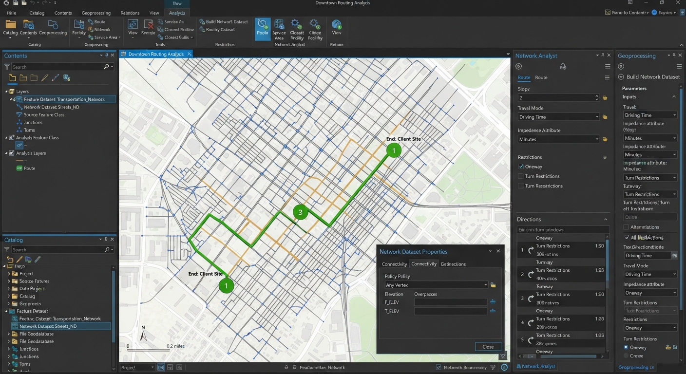
Create Network Dataset ArcGIS Pro: Step-by-Step Guide
When completing transportation or urban planning assignments in desktop GIS, standard straight-line Euclidean distance calculations are rarely sufficient. Real-world mobility depends on transportation infrastructure: streets, one-way restrictions, speed limits, overpasses, and turn rules. Knowing how to create network dataset ArcGIS Pro structures from raw line centerlines is a core skill for solving routing problems, mapping drive-time service areas, or finding the closest emergency response facility.
Unlike simple polyline shapefiles, a network dataset models topological connectivity and directional impedance across complex road networks. This tutorial guides you through the process of preparing your street centerline geometry, configuring geodatabase feature datasets, setting up cost evaluators, and building a fully functional routing network.
Quick Navigation / Table of Contents
-
Core Concepts: How Network Datasets Model Transportation
-
Step 1: Prepare Street Centerline Geometry and Topology
-
Step 2: Set Up a Geodatabase Feature Dataset
-
Step 3: Step-by-Step Guide to Create Network Dataset ArcGIS Pro Workflows
-
Step 4: Build, Validate, and Test Routing Solvers
-
Pro Tip: Modeling Overpasses and Underpasses with Elevation Fields
-
Frequently Asked Questions (FAQ)
-
Conclusion & Lab Summary
1. Fundamentals of Network Analysis in ArcGIS Pro
A Network Dataset is an advanced spatial data structure in ArcGIS Pro that models the flow of agents—such as automobiles, delivery trucks, pedestrians, or emergency vehicles—across an interconnected network of edge (line) and junction (point) elements.
+-------------------------------------------------------------------------+
|                       RAW STREET CENTERLINE LINES                       |
|           Polylines with Speed Limits, Length, & One-Way Fields         |
+------------------------------------+------------------------------------+
                                     |
                                     v
                  +-------------------------------------+
                  |      GEODATABASE FEATURE DATASET    |
                  | Enforces Spatial Reference & Rules  |
                  +------------------+------------------+
                                     |
                                     v
                  +-------------------------------------+
                  |       CREATE NETWORK DATASET        |
                  |  Defines Edges, Junctions, & Turns  |
                  +------------------+------------------+
                                     |
            +------------------------+------------------------+
            |                                                 |
            v                                                 v
  [ Cost Attributes ]       [ Restrictions ]         [ Evaluators & Travel Modes ]
  Drive Time (Minutes)      One-Way Streets          Car, Truck, Walking
  Distance (Meters)         Height/Weight Limits     Impedance Calculations
Key Components of a Routing Network
-
Edges: Line features representing travel paths (e.g., street segments, highway links, footpaths).
-
Junctions: Point features connecting edges and facilitating transfer between paths (e.g., street intersections).
-
Turns: Optional feature classes that store directional delay rules or illegal turn restrictions (e.g., “No Left Turn between 7 AM and 9 AM”).
-
Impedance (Cost): The resistance or metric consumed when traversing network elements (e.g., distance in meters or travel time in minutes).
2. Step 1: Prepare Street Centerline Geometry and Topology
The single most common reason network datasets fail to solve routes in university lab assignments is poor centerline geometry. Before building a network dataset, your source polylines must meet strict topological standards.
Essential Line Preparation Checks
-
-
Split at Intersections: Street polylines must be split at every point where vehicles can transition from one street to another. If two crossing lines do not share a vertex or endpoint at their intersection, the network solver treats them as an overpass/underpass with no connection.
-
Eliminate Multipart Features: Network edges must be single-part line features. Run the Multipart To Singlepart tool (Data Management Tools > Features) to ensure every segment is an independent feature.
-
Clean Up Geometry Overshoots & Dangles: Ensure dead-end streets end cleanly and connecting roads touch precisely without overshoot or undershoot gaps. Use snapping during editing to maintain geometry precision.
-
Required Attribute Fields: Verify your attribute table contains necessary fields for routing calculations:
-
Length Field: Segment distance in meters or feet (
Shape_Lengthor custom field). -
Speed Limit Field: Numeric speed limit (
Speed_MPHorSpeed_KPH). -
Drive Time Fields: Double fields calculated from distance and speed:
DriveTime_FT(From-To direction) andDriveTime_TF(To-From direction). -
One-Way Direction Field: Text field indicating flow restrictions (e.g.,
FT= One Way From-To,TF= One Way To-From,B= Both directions allowed,N= No traffic allowed).
-
-
3. Step 2: Set Up a Feature Dataset in a File Geodatabase
In ArcGIS Pro, network datasets cannot exist as standalone shapefiles or loose geodatabase feature classes. They must be stored inside a Feature Dataset within a File Geodatabase (
.gdb) or Enterprise Geodatabase.Creating the Feature Dataset Container
-
Open the Catalog Pane (View > Catalog Pane).
-
Expand your project directory, right-click your File Geodatabase, and select New > Feature Dataset.
-
Name your feature dataset (e.g.,
Transportation_Network). -
Coordinate System Selection: Assign a local Projected Coordinate System (PCS) (e.g., State Plane or UTM Zone). Do not use unprojected WGS84 lat/long degrees, as linear distance metrics and cost evaluators require projected meters or feet.
-
Import your prepared street centerline feature class into this new Feature Dataset using Feature Class To Geodatabase or by dragging the layer in.
<=”carousel-container”>
Step 1: Launch the Create Network Dataset Tool
-
In the Catalog Pane, right-click your Feature Dataset (
Transportation_Network). -
Select New > Network Dataset.
-
Name your network dataset (e.g.,
Streets_ND). -
Select your street centerline feature class as the input source edge feature class.
Step 2: Configure Elevation and Connectivity Settings
-
Connectivity Policy: Choose End Point (routes transition only at line endpoints) or Any Vertex (routes transition anywhere lines touch). For properly split street centerlines, End Point is standard.
-
Elevation Model: Select Z-Coordinates if your lines contain 3D Z-values, or Elevation Fields if using
F_ELEVandT_ELEVinteger fields to control grade-separated intersections (e.g., bridges and tunnels).
Step 3: Configure Cost Attributes and Evaluators
-
Navigate to the Attributes configuration tab.
-
Add a new Cost Attribute named Meters (Units: Meters, Data Type: Double). Set evaluators to map directly to
Shape_Length. -
Add a new Cost Attribute named DriveTime (Units: Minutes, Data Type: Double).
-
Configure Evaluators for
DriveTime:-
Assign
DriveTime_FTfor the From-To edge direction. -
Assign
DriveTime_TFfor the To-From edge direction.
-
-
Add a Restriction Attribute named Oneway:
-
Set evaluator type to Field Script / Expression.
-
Map the restriction to your
Onewaytext column so thatFTrestricts To-From travel,TFrestricts From-To travel, andNblocks both directions.
-
Step 4: Define Travel Modes
-
Click the Travel Modes tab.
-
Create travel profiles tailored to your assignment scenarios:
-
Driving Time: Primary cost set to
DriveTime(Minutes), restrictions applied toOneway. -
Driving Distance: Primary cost set to
Meters, restrictions applied toOneway. -
Walking: Primary cost set to
WalkingTime, ignoringOnewayrestrictions (since pedestrians can walk both directions along streets).
-
-
Click Finish / Run to build the network schema.
Pro Tip: Grade-Separated Intersections with Elevation Fields
A common flaw in student network models is allowing illegal turns where an overpass bridge crosses over a highway. Because two lines cross in 2D space, the network solver might create an artificial junction unless elevation rules are defined.To fix this, add two integer fields to your street centerline layer:
F_ELEV(From-Node Elevation):0for ground level,1for elevated bridge.T_ELEV(To-Node Elevation):0for ground level,1for elevated bridge.In the Network Dataset Properties wizard under Elevation Fields, set the From-elevation and To-elevation properties to these fields. Two crossing lines with different elevation values at the intersection point will not connect topologically, maintaining realistic overpass and underpass routing.
5. Step 4: Build, Validate, and Test Routing Solvers
Creating the network dataset wizard schema creates the metadata structure, but you must explicitly Build the network to construct index matrices and junction geometries.
Building the Network
-
In the Catalog Pane, right-click your newly created network dataset (
Streets_ND). -
Click Build Network.
-
Once completed, ArcGIS Pro generates system junction point layers (
Streets_ND_Junctions) inside your Feature Dataset.
Testing with Network Analyst Solvers
-
-
On the main top ribbon, click the Analysis tab.
-
Click Network Analyst and select Route (or Service Area / Closest Facility).
-
In the Network Analyst tab, set the Network Dataset target to your built
Streets_ND. -
Open the Import Stops tool and add two or more location points on your map scene.
-
Select your Travel Mode (e.g., Driving Time).
-
Click Run. The Network Analyst extension calculates and draws the optimal route following one-way rules, turn restrictions, and speed limits.
- To explore shortest path algorithms further, check out our guide on Network Analysis Shortest Path Calculations
-
-
For official algorithm parameters, consult the Esri Network Analyst Documentation.
6. Frequently Asked Questions (FAQ)
Why does my network dataset require a File Geodatabase feature dataset?
Network datasets require a Feature Dataset container to enforce a shared spatial reference system across all edge, junction, and turn feature classes, ensuring spatial alignment and topological integrity across the network.
How do I set up one-way street restrictions in my attribute table?
Create a text attribute field (e.g.,
Oneway) and populate it with standardized values: FT (one-way in digitized line direction), TF (one-way opposite line direction), B (two-way traffic allowed), or N (no travel allowed). Map this field to a Restriction attribute in the network properties.What is the difference between a geometric network and a network dataset?
Geometric networks are legacy Esri data structures designed primarily for directed utility flows (such as water pipes or electric grids where flow follows pressure or gravity). Network datasets are designed for multi-directional agent routing (such as cars or pedestrians) with complex turns, speed limits, and travel modes.
7. Conclusion & Summary
Mastering how to create network dataset ArcGIS Pro structures enables advanced spatial analysis beyond simple proximity buffering. By preparing topological line centerlines, structuring File Geodatabase feature datasets, setting up drive-time evaluators, and configuring one-way restrictions, you can model real-world transportation networks for any university assignment.
Key Takeaways:
-
Always use a Projected Coordinate System (PCS) for your feature dataset.
-
Ensure street centerlines are split at valid intersections and converted to single-part features.
-
Map impedance evaluators (
DriveTime,Distance) and directional restrictions (Oneway) accurately. -
Always execute Build Network after modifying source geometries or attribute parameters.