
When starting introductory Geographic Information Systems (GIS) coursework, university students often face a fundamental task: turning raw imagery into usable vector data. Learning how to digitize boundaries in GIS applications is an essential skill, whether you are creating land-use polygons from georeferenced historical maps, tracing building footprints from high-resolution satellite basemaps, or mapping river channels.
Manual vector digitizing requires precision. Without setting up proper snapping rules and vector editing settings, digitizing can quickly introduce topological errors like sliver polygons, boundary gaps, or overlapping geometries. This step-by-step tutorial covers everything you need to create clean point, line, and polygon feature classes in both QGIS and ArcGIS Pro.
Quick Navigation / Table of Contents
-
Core Concepts: Heads-Up Digitizing & Topological Integrity
-
Step 1: Create an Empty Vector Dataset with a Projected CRS
-
Step 2: Configure the Snapping Environment & Tolerance Radius
-
Step 3: Step-by-Step Guide to Digitize Boundaries in GIS (QGIS & ArcGIS Pro)
-
Step 4: Populate Attribute Tables During Feature Creation
-
Pro Tip Callout: Preventing Slivers, Gaps, and Topology Errors
-
Frequently Asked Questions (FAQ)
-
Conclusion & Lab Summary
1. Fundamentals of Heads-Up Digitizing in GIS
Before clicking on your canvas to place points, it is important to understand the process of heads-up digitizing (also known as on-screen digitizing).
+-------------------------------------------------------------------------+
|                       GEOREFERENCED RASTER BASEMAP                       |
|          Aerial Photograph, Satellite Image, or Historical Map          |
+------------------------------------+------------------------------------+
                                     |
                                     v
                  +-------------------------------------+
                  |     SNAPPING ENVIRONMENT SETUP      |
                  | Sets Vertex, Edge, & Radius Limits  |
                  +------------------+------------------+
                                     |
                                     v
                  +-------------------------------------+
                  |      MANUAL FEATURE DIGITIZING      |
                  | Tracing Vertices (Point/Line/Area)  |
                  +------------------+------------------+
                                     |
            +------------------------+------------------------+
            |                                                 |
            v                                                 v
  [ Point Digitizing ]       [ Line/Polyline ]        [ Polygon Boundaries ]
  Trees, Wells, Signs        Roads, Streams           Parcels, Lakes, Zoning
What is Digitizing?
Digitizing is the process of converting geographic data from raster imagery or hardcopy paper maps into vector features (points, lines, or polygons).
-
Points: Zero-dimensional features representing discrete locations (e.g., soil sample locations or water wells).
-
Lines / Polylines: One-dimensional features representing linear networks (e.g., rivers, roads, or utility lines).
-
Polygons: Two-dimensional closed shapes representing area boundaries (e.g., land parcels, forest stands, or lakes).
To learn how to fix geometry errors after feature creation, refer to our guide on
[Internal Link Context: Suggest linking to related article on Fix Topology Errors in GIS].2. Step 1: Create an Empty Vector Dataset
To digitize boundaries, you must first create an empty vector container to store your geometries and attribute columns.
Creating a New Vector Layer in QGIS
-
Launch QGIS and go to Layer > Create Layer > New Shapefile Layer… (or New GeoPackage Layer…).
-
Set the file destination and layer name.
-
Select the Geometry type (Point, LineString, or Polygon).
-
Assign the Spatial Reference System (CRS): Choose a local Projected Coordinate System (PCS) (e.g., UTM Zone 19N) rather than an unprojected geographic system (WGS84). This ensures distance and area calculations remain accurate.
-
Add custom attribute fields (e.g.,
LandUse_Typeas String,Parcel_Areaas Decimal) under New Field and click Add to Fields List. -
Click OK.
Creating a New Feature Class in ArcGIS Pro
-
Open ArcGIS Pro, expand your project database in the Catalog Pane, right-click your
.gdb, and select New > Feature Class. -
Type a Name and select the Feature Class Type (Polygon, Polyline, or Point).
-
Add desired field names and data types in the Fields window.
-
Set the Spatial Reference to match your project’s local projected coordinate system and click Finish.
3. Step 2: Configure the Snapping Environment
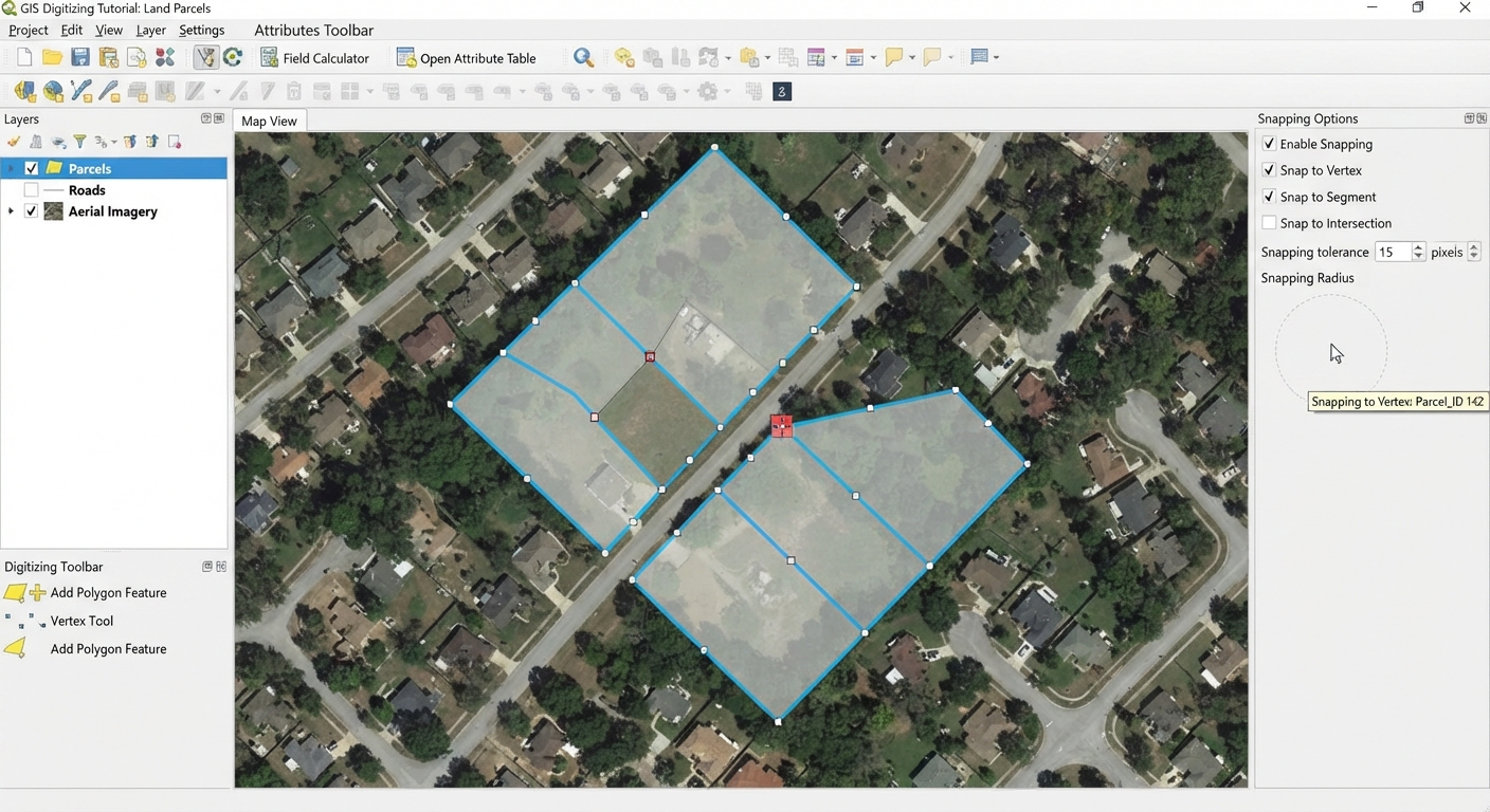
The snapping environment automatically pulls your cursor to existing vertices, lines, or edges within a user-defined search distance. Snapping is essential for ensuring shared parcel boundaries connect cleanly without gaps or overlaps.
Key Snapping Settings
-
Snapping Tolerance: The search radius surrounding your cursor (typically set between 5 to 15 pixels or 1 to 5 meters). When your cursor falls within this distance of an existing feature, it locks directly onto it.
-
Vertex Snapping: Snaps your cursor precisely to existing boundary corners or point nodes.
-
Edge / Segment Snapping: Snaps your cursor anywhere along an existing feature’s line segment.
-
Intersection Snapping: Snaps your cursor to locations where two lines cross.
For comprehensive details on advanced snapping options, explore the official QGIS Editing Documentation.
4. Step 3: Step-by-Step Guide to Digitize Boundaries in GIS
With your snapping environment active, you are ready to trace features from your basemap image.
Digitizing Boundaries in QGIS
-
Select your target vector layer in the Layers Panel.
-
Click the yellow pencil icon (Toggle Editing) on the Digitizing Toolbar.
-
Click the Add Polygon Feature tool.
-
Left-click along your basemap image to place vertices around your feature boundary.
-
To share an adjacent border, hover over the existing boundary until the snapping indicator appears, left-clicking along existing nodes.
-
Right-click anywhere on the map view to close and finalize the polygon boundary.
-
Fill out the attribute prompt pop-up box and click OK.
Digitizing Boundaries in ArcGIS Pro
-
Select the Edit tab on the top ribbon.
-
Click Create to open the Create Features Pane.
-
Click your target layer and select the Polygon or Autocomplete Polygon tool.
-
Left-click on your map scene to place boundary nodes.
-
Use the Trace Tool on the editing palette to trace along existing feature edges automatically.
-
Double-click or press F2 to finish the feature sketch.
-
Click the Save button on the Edit tab to save your edits to the geodatabase.
Pro Tip: Preventing Slivers and Topology Errors
5. Step 4: Attribute Editing During Digitization
A vector dataset consists of both spatial geometry and descriptive alphanumeric attributes.
-
Populating Attributes On-the-Fly: Configure your editor settings so the attribute form opens immediately after finishing each geometry.
-
Batch Attribute Updating: If you are digitizing dozens of features belonging to the same category (e.g., forest stands), select all newly digitized features in the attribute table and use the Field Calculator to populate values across multiple rows simultaneously.
-
Saving Edits Regularly: Digitized geometries reside in temporary memory cache until saved. Save your edits frequently (Edit > Save in ArcGIS Pro, or click Toggle Editing to save in QGIS) to prevent loss of work.
6. Frequently Asked Questions (FAQ)
What is the snapping environment in GIS and why is it crucial for digitizing?
The snapping environment automatically locks your cursor to existing nodes, vertices, or edges within a specified tolerance distance. It is crucial because it eliminates human placement error, preventing gaps and overlaps between adjacent boundary features.
How do I split or reshape an existing digitized polygon?
Select the target feature, then use the Split Features tool (or Reshape Features tool) on the edit toolbar. Draw a line completely cutting across the feature to divide it into two distinct polygons, or sketch a new outer edge to reshape it.
What is stream digitizing vs vertex-by-vertex digitizing?
Vertex-by-vertex digitizing requires manual left-clicking to place every individual point node along a line or polygon. Stream digitizing automatically generates vertices at set time or distance intervals as you move your cursor across the screen.
7. Conclusion & Summary
Mastering vector digitizing workflows is a cornerstone skill for spatial analysis coursework. By setting up structured feature layers with appropriate projected coordinate systems, configuring snapping tolerance radii, and using topological editing tools like autocomplete polygons, you can build clean, topology-error-free vector layers for any GIS lab assignment.
Key Takeaways:
-
Always use a Projected Coordinate System (PCS) for accurate spatial measurements.
-
Enable Snapping (5-15 pixels) before placing your first vertex.
-
Use Autocomplete Polygon tools to draw shared borders and avoid sliver gaps.
-
Save your editing session often to prevent lost work.