
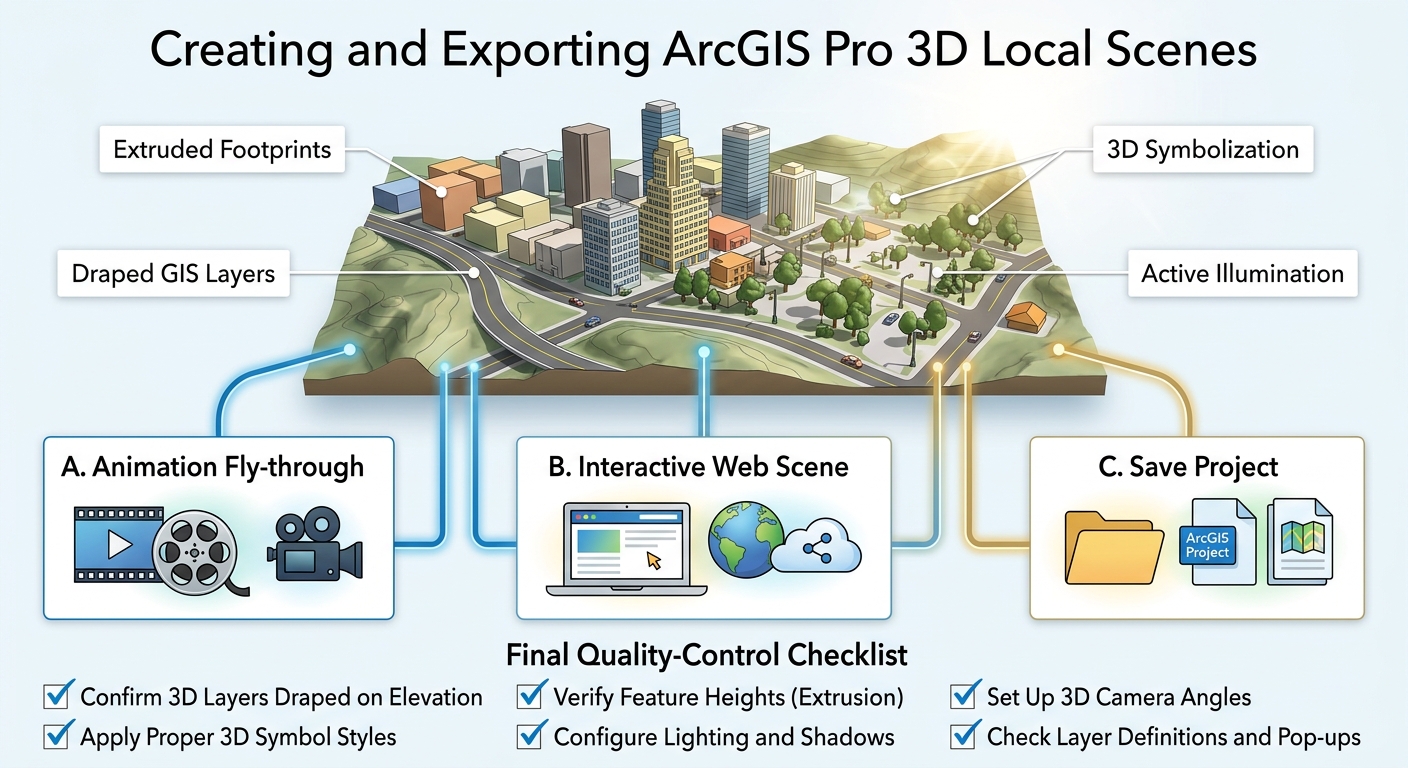
3D Scene Creation in ArcGIS Pro: Converting 2D Features into Elevation-Aware Models
1. Introduction: Why Create 3D GIS Scenes?
When learning how to build a 3D Scene ArcGIS Pro 2D features project, analysts must first understand the transition from flat 2D surfaces to elevation-aware models.Traditional GIS maps display geographic information on a flat, two-dimensional surface. Although 2D maps are effective for presenting spatial distributions, they cannot always communicate the height, shape, or vertical relationships of real-world features.
For example, a 2D urban map can show roads and building footprints, but it cannot easily demonstrate how tall buildings are, how they relate to surrounding terrain, or how a proposed structure may affect views from nearby locations.
3D GIS visualization introduces the vertical dimension into spatial analysis, making geographic relationships easier to understand and communicate.
ArcGIS Pro provides a 3D scene environment in which you can combine terrain elevation, building footprints, roads, land-use polygons, satellite imagery, and 3D symbols.
Common applications include:
- Urban planning: Visualizing building heights, development density, and proposed construction.
- Environmental impact assessment: Examining terrain, vegetation, and the visual context of proposed infrastructure.
- Flood risk communication: Displaying terrain in 3D and visualizing water-level scenarios when supported by suitable elevation and modelling data.
- Student presentations: Turning conventional GIS layers into interactive scenes that communicate spatial relationships more intuitively.
- Infrastructure planning: Examining roads, buildings, and terrain together to understand potential design constraints.
This guide demonstrates how to transform a conventional 2D GIS project into an elevation-aware 3D scene in ArcGIS Pro, using a local study area as an example.
The workflow covers scene creation, elevation surfaces, draping, building extrusion, lighting, performance optimization, and exporting your final work.
2. Setting Up Your Environment: Global vs. Local Scenes
Before converting your 2D features into 3D, decide which scene type suits the project.
ArcGIS Pro supports two main viewing modes: Global Scene and Local Scene. They are designed for different geographic extents and visualization needs. See Esri’s Scenes documentation.
Global Scene
A Global Scene displays geographic information in a globe-based environment. It is useful when the curvature of the Earth matters or when the study covers a very large geographic area.
Typical applications include:
- Worldwide flight paths.
- Global environmental datasets.
- Continental-scale elevation patterns.
- Large-scale spatial phenomena viewed in a global context.
Global scenes use a geographic coordinate system appropriate to the global viewing environment. ArcGIS Pro documents WGS 84 and CGCS 2000 as supported coordinate systems for global scenes.
Local Scene
A Local Scene displays a smaller area, such as a city, campus, construction site, or neighbourhood. It is particularly suitable for 3D visualization using projected coordinate systems.
Typical applications include:
- City-centre building models.
- Campus planning.
- Terrain and infrastructure visualization.
- Local environmental impact assessments.
- Extruding building footprints using height attributes.
For most university projects that convert ordinary vector layers into a 3D model, a Local Scene is the recommended starting point.
| Feature | Global Scene | Local Scene |
|---|---|---|
| Geographic extent | Global or very large | Local or regional |
| Earth curvature | Displayed | Localized scene view |
| Projected coordinate systems | Limited global-scene support | Supported |
| Building extrusion | Supported | Supported |
| Terrain visualization | Supported | Supported |
| Typical project | Global environmental patterns | Urban planning or campus models |
Prepare your source data
Before proceeding, make sure your project contains:
- A suitable elevation raster, such as a DEM.
- Building footprints stored as polygons.
- A numeric building-height field, if buildings will be extruded by their recorded heights.
- Roads, land-use polygons, and other contextual layers.
- A suitable coordinate reference system for the study area.
For the building-height example, assume the footprint attribute table contains a field named HEIGHT_M, storing each building’s height in metres.
If the field contains the number of floors rather than actual height, you would need a documented method to estimate building height before using it for extrusion.
3. Step 1: Convert a 2D Map into a 3D Local Scene
The first step is creating a scene containing the layers from your existing 2D map.
ArcGIS Pro allows you to convert a map to a scene without removing or modifying the original map. The new scene contains the map’s layers and an elevation surface for 3D visualization.
Procedure
-
Open your ArcGIS Pro project.
-
Activate the 2D map you want to convert by clicking its view tab.
-
On the ribbon, click the View tab.
-
In the View group, click Convert.
-
Choose To Local Scene.
-
Wait for ArcGIS Pro to create the scene and make it the active view.
-
Review the Contents pane to confirm that the layers have been carried into the new scene.
The scene and the original map are separate project items. Changes to layer visibility or scene display settings do not automatically change the equivalent settings in the original map, although edits to shared source data affect both views.
Official instructions: Convert a map to a scene.
Understand the Contents pane
In a 3D scene, layers are generally organized into these categories:
- 2D Layers: Typically contain information draped onto the ground surface, such as roads, imagery, and land-use polygons.
- 3D Layers: Contain content positioned independently in 3D space or drawn with 3D symbology, such as extruded buildings.
- Elevation Surfaces: Contain the ground and any additional elevation surfaces used to position features.
The ground surface provides a vertical reference for features that need to follow the terrain.
Navigate the scene
Use the scene navigation controls to inspect your study area from different angles.
-
Zoom in to examine roads and building footprints.
-
Tilt the view to see the terrain from an oblique perspective.
-
Rotate the scene to inspect the area from another direction.
-
Return to a useful viewing angle before styling your layers.
A 3D scene can contain accurate spatial data and still be difficult to interpret if the camera angle is too low, the map extent is poorly framed, or the model is cluttered.
Tip: Save the project after conversion. Your original 2D map remains available if you need to return to conventional cartographic analysis.
4. Step 2: Set the Ground Elevation Surface Using a DEM
A 3D scene without meaningful elevation data may display its content on a flat plane. To show hills, valleys, slopes, and changes in terrain height, you need an elevation source.
A Digital Elevation Model (DEM) stores elevation values in raster cells. ArcGIS Pro can use a DEM or a suitable elevation service to define the ground elevation surface.
Each cell’s elevation contributes to the 3D shape of the terrain.
Option A: Use a DEM stored on your computer
Use this option when you already have an appropriate local elevation raster.
Procedure
-
Add the DEM to your ArcGIS Pro project using Map → Add Data.
-
Confirm that the raster covers your study area and contains valid elevation values.
-
In the Contents pane, right-click the raster layer.
-
Look for the elevation-surface command, such as Add to Ground, or use the Ground elevation surface’s context menu to add an elevation source.
-
Confirm that the DEM is being used as an elevation source rather than merely displayed as a coloured image.
-
Inspect the terrain in the scene.
The Ground elevation surface is a composite layer, and it can use multiple elevation sources. Higher-resolution sources should generally be placed appropriately in the elevation-source order so they are used where their coverage is available.
See Esri’s Elevation source layers guide.
Option B: Use an online elevation service
If your ArcGIS Pro project has an internet connection and suitable portal access, you may be able to use an available elevation service.
New Local and Global Scenes commonly contain a default Terrain 3D elevation source when connected to ArcGIS Online. This provides tiled elevation for visualization.
Procedure
-
Expand the Elevation Surfaces section in the Contents pane.
-
Expand Ground to inspect its elevation sources.
-
Check whether a suitable elevation source is already available.
-
If needed, add a compatible elevation layer or service to Ground.
-
Navigate around the scene to verify that the terrain follows the expected elevation pattern.
If the default elevation service cannot be accessed, the scene may appear flat. You can then add a suitable local DEM.
Important: The default Terrain 3D service is intended for scene visualization, not as a substitute for an appropriate analytical DEM in geoprocessing. For quantitative terrain analysis, use a dataset with appropriate spatial resolution, vertical units, coverage, and documented accuracy.
Check the elevation units
A common error is mixing horizontal and vertical units.
For example, the DEM’s coordinates may be projected in metres while its elevation values are recorded in feet.
-
Open the elevation source’s properties.
-
Check the spatial reference and elevation units.
-
Confirm that the elevation values use the expected vertical units.
-
Apply an appropriate vertical-unit correction if the source requires it.
ArcGIS Pro provides vertical-unit settings for supported elevation sources. Incorrect vertical units can make a scene’s terrain appear excessively steep or unnaturally flat.
Adjust vertical exaggeration
Vertical exaggeration increases the apparent vertical relief of the scene. It can help reveal subtle terrain differences, but excessive exaggeration may misrepresent the real landscape.
-
Select the Ground elevation surface in the Contents pane.
-
Open its Elevation Surface Layer ribbon options.
-
Locate the vertical exaggeration setting.
-
Start with the default value and adjust only when necessary.
-
Inspect whether hills and slopes still look plausible relative to buildings and other features.
For scientific or engineering presentations, keep vertical exaggeration at 1 unless there is a clear reason to use a different value, and always disclose any exaggeration used.
5. Step 3: Drape Vector Layers onto the Terrain
Once the ground surface has meaningful elevation, position the other GIS layers so that they follow that surface.
Draping means displaying a 2D layer on an elevation surface without giving each feature its own independent 3D geometry.
It is useful for roads, satellite imagery, land-use polygons, administrative boundaries, and other layers that should follow the terrain.
5.1 Drape roads and land-use polygons
In a scene, layers in the 2D Layers category are commonly displayed on the ground.
Procedure
-
Add the road network and land-use polygon layers if they are not already in the scene.
-
In the Contents pane, keep them in the 2D Layers category if they should drape on Ground.
-
Right-click each layer and choose Properties.
-
Open the Elevation tab.
-
Confirm that the elevation mode is appropriate, such as On the Ground.
-
Click Apply and OK.
-
Inspect roads and polygons in the scene.
You should see road lines and land-use polygons following the topography rather than remaining suspended at an unrelated height.
5.2 Fix layers that appear to float or sink
If roads appear above the terrain or building footprints seem buried inside it, inspect their elevation properties and source coordinates.
Potential causes include:
- Incorrect elevation mode.
- Unrecognized or missing Z-values.
- Vertical-unit mismatches.
- A mismatch between data elevations and the terrain surface.
- Invalid source coordinates or an unsuitable spatial reference.
For layers that represent ground features, On the Ground is a useful starting point. Features that have true elevation values or represent objects above the surface may require another elevation mode.
Esri describes these settings in Define height characteristics for layers.
5.3 Style draped layers
Draped features must remain clear when viewed from an oblique angle.
-
Use contrasting road colours and line widths.
-
Keep administrative boundaries visually subtle.
-
Use simple colours for land-use polygons.
-
Avoid overly thick lines that obscure terrain.
-
Reduce the opacity of reference imagery when it competes with thematic layers.
For example, a road network may use light grey lines, while major highways have thicker, darker lines. Land-use polygons can use restrained colours that distinguish land-cover classes without overwhelming the elevation model.
Tip: Not every layer should be 3D. Draping roads and boundaries often creates a clearer scene than giving every feature unnecessary height or geometry.
6. Step 4: Extrude Building Footprints Using Height Attributes
Building extrusion is one of the most effective ways to transform a basic 2D map into an urban 3D model.
Extrusion stretches a flat polygon vertically, producing a 3D-looking building whose height is controlled by an attribute or expression.
For example, a footprint with a height of 12 metres can be displayed as a building extending 12 metres above its base elevation, provided the correct extrusion type and elevation settings are used.
<AsyncImage query=”ArcGIS Pro local 3D urban scene extruded building footprint polygons realistic buildings terrain roads oblique view GIS visualization” aspectRatio=”16:9″ width=”100%”/>
6.1 Inspect the building attributes
Before extruding, ensure that the building layer contains a suitable height field.
-
In the Contents pane, right-click Building Footprints.
-
Select Attribute Table.
-
Identify a numeric field containing building height, such as
HEIGHT_M. -
Check that values are populated and use consistent units.
-
Investigate missing, zero, negative, or implausibly large height values.
If the height information is stored as text, clean or convert it to a numeric field first.
If only the number of floors is available, you can create an estimated height field using an explicitly justified average floor height. Document that the resulting buildings are approximate models, not surveyed heights.
6.2 Enable extrusion
-
Select Building Footprints in the Contents pane.
-
On the ribbon, open the contextual Feature Layer tab.
-
Locate the Extrusion group.
-
Open the Extrusion Type drop-down.
-
Choose Max Height for a building-height field representing the top height of each building.
-
In the Field drop-down, choose
HEIGHT_M. -
Set the extrusion unit to Meters.
-
Confirm that the buildings now appear as 3D shapes.
The exact extrusion option matters. If your data field describes the height of the building above ground, a suitable height extrusion should extend the footprint upward from the feature’s base. If the field instead contains absolute elevations for building tops or bases, choose a corresponding method after inspecting the data definition.
ArcGIS Pro supports extrusion for point, line, and polygon features. See Extrude features to 3D symbology.
6.3 Choose suitable extrusion settings
Different extrusion types support different meanings.
| Extrusion concept | When it may be appropriate |
|---|---|
| Extrude by a height field | Each footprint has a measured or estimated building height |
| Base height plus an extrusion height | The feature has a defined base elevation and a separate height |
| Extrude by a statistic or expression | Height is calculated from other attributes |
| Absolute height | Features are positioned using an absolute elevation reference |
Check the unit of the height field before applying extrusion. A field measured in feet should not be interpreted as metres.
For an ordinary urban building model, the height of a footprint and the terrain elevation at its base are separate concepts: the elevation surface positions the building on the terrain, while extrusion determines its vertical height.
6.4 Apply realistic 3D symbology
Basic extrusion produces useful massing models, but styling improves the scene’s appearance and readability.
-
Adjust the building fill colour.
-
Use subtle side-face shading and outlines.
-
Keep the roof colour and building walls visually consistent where appropriate.
-
Use realistic materials only when they add value to the analysis.
-
Avoid excessively reflective or highly saturated colours.
-
Check that smaller buildings remain visible at the chosen scene scale.
For a planning assignment, simple, neutral building colours often work better than highly realistic materials because they keep the focus on building heights, spacing, and the spatial arrangement of urban development.
Important: Display extrusion creates a 3D visualization from the source geometries; it does not automatically convert every footprint into a fully modelled architectural building. If you need detailed roof shapes, construction geometry, or physically modelled solids, you may need actual 3D building data or other modelling workflows.
7. Step 5: Apply Lighting, Shadows, and Scene Presentation
Once the terrain and building models are configured, improve how the scene communicates elevation and shape.
Lighting and shadows help readers interpret vertical structures and terrain relief. However, too much shading can hide roads, obscure small features, or make a scene look more dramatic than informative.
7.1 Adjust scene lighting
-
Make the scene active.
-
Click the View tab.
-
In the Scene group, locate the illumination controls or Illumination manager.
-
Adjust the time of day to change the direction of sunlight.
-
Enable or disable shadows as appropriate.
-
Adjust ambient illumination to preserve detail in shaded areas.
-
Inspect buildings from more than one angle.
ArcGIS Pro supports illumination settings such as time of day, sun shadows, and ambient light. These controls are available through the Scene group’s illumination tools and the scene’s properties. See Scenes and illumination properties.
7.2 Use shadows to explain space
Shadows can help visualize:
- Building height differences.
- Street-canyon geometry.
- Potential shading among buildings.
- Terrain relief.
- The relative position of structures.
For urban planning, shadows may illustrate a scenario at a selected sun angle and time. They should not be treated as a full solar-access or building-energy analysis without suitable methods and settings.
If your assignment examines solar access, record the date, time, location, and relevant scene assumptions.
7.3 Choose the right viewing mode
ArcGIS Pro supports perspective and parallel drawing modes.
- Perspective mode resembles human vision: objects appear smaller as they recede into the distance. This usually works well for presentation and fly-throughs.
- Parallel mode avoids the visual size change caused by perspective. It can be helpful for architectural-style visualizations and comparing the sizes of extruded shapes.
To change modes, click the View tab and locate Drawing Mode in the Scene group.
Use the mode that best serves the communication goal rather than choosing the most dramatic view.
8. Performance Tips: Managing GPU Usage and Rendering Speed
3D scenes can be resource-intensive, especially when they contain detailed terrain, thousands of building footprints, high-resolution imagery, and complex 3D symbols.
ArcGIS Pro uses the graphics processing unit (GPU) for scene rendering. When available graphics resources are exceeded, you may notice low frame rates, incomplete drawing, or a GPU-resource warning. Esri’s GPU resources guide recommends reducing scene complexity and adjusting display settings.
Improve performance
- Reduce unnecessary detail. Simplify dense line and polygon geometries when the full precision is not needed for display.
- Limit visible distances. Hide distant buildings or detailed layers when they are not useful at a particular viewing scale.
- Use 2D Layers where appropriate. Roads, boundaries, and imagery that only need to drape on the surface generally do not need independent 3D geometry.
- Reduce rendering quality during navigation. Open Project → Options → Display and adjust the rendering-quality setting if needed.
- Use simpler symbols. Reduce complex materials and high-detail symbols when they do not improve the analysis.
- Close unnecessary views. Multiple open scenes can increase graphics-resource demand.
- Prepare suitable data resolutions. Avoid loading unnecessarily detailed rasters for broad-area views.
If the scene uses several thousand buildings, consider whether the entire dataset needs to be visible simultaneously. A reduced study area, generalized buildings, or distance-dependent visibility can significantly improve navigation.
Performance rule: Make the scene as simple as possible for the current scale, while preserving the geographic information needed for the analysis.
9. Conclusion and Exporting Options
Once the 3D scene is complete, choose an output format that suits the assignment or audience.
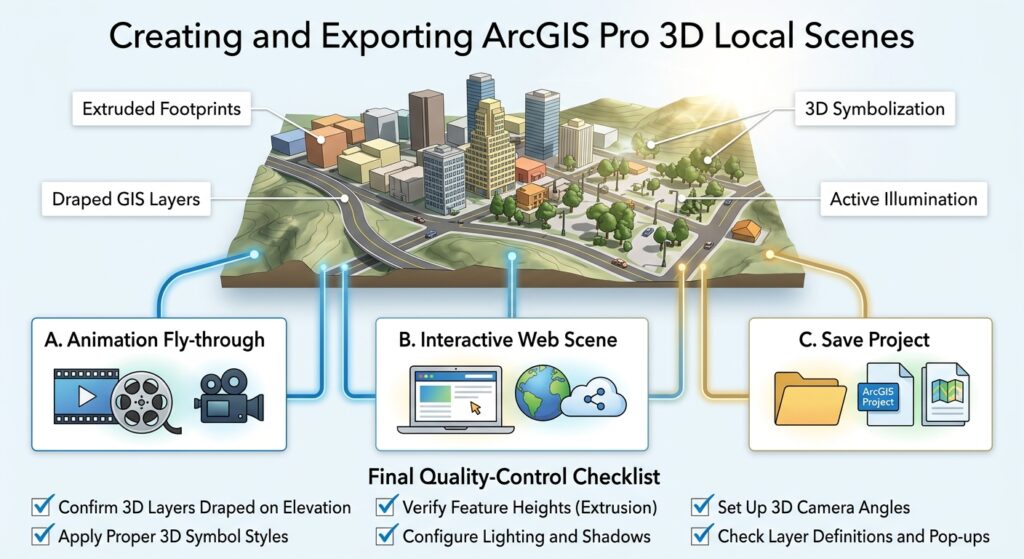
Option A: Save the ArcGIS Pro project
Use Project → Save to retain the scene, layer symbology, elevation settings, extrusion configurations, and other project information.
This is the best option when the recipient needs to continue editing the scene in ArcGIS Pro. Make sure the source data remains available and accessible.
Option B: Export a fly-through animation
A fly-through can show the scene from multiple viewpoints and communicate how buildings, roads, and terrain relate spatially.
Procedure:
-
Make the scene active.
-
Click View → Add Animation.
-
Create the first keyframe at the starting camera position.
-
Navigate to another viewpoint and append additional keyframes.
-
Adjust transitions, duration, and pauses to create a smooth camera path.
-
Preview the animation.
-
On the Animation tab, click Export Movie.
-
Select a suitable format, resolution, frame rate, and quality setting.
See Esri’s Create an animation and Export an animation documentation.
For a university presentation, a short, controlled fly-through is often more effective than fast camera movement or excessive rotation.
Option C: Share an interactive web scene
If the project should be explored in a browser, share the scene to ArcGIS Online or ArcGIS Enterprise.
Procedure:
-
Sign in to the appropriate ArcGIS portal.
-
Open the completed scene.
-
Click the Share tab.
-
In the Share As group, select Web Scene.
-
Enter the scene’s title, summary, tags, and sharing settings.
-
Review the configuration and analyze the scene for potential errors or performance problems.
-
Resolve required errors and review warnings.
-
Click Share and confirm that the published scene can be opened in Scene Viewer.
Sharing a web scene generally requires suitable account privileges to create content and publish the necessary web layers. See Share a web scene.
Final quality-control checklist
Before submitting your 3D GIS assignment, confirm the following:
-
The scene uses the appropriate local or global viewing mode.
-
Terrain elevation is valid and uses correct vertical units.
-
Roads and other 2D layers are positioned correctly on the terrain.
-
Building footprints are extruded using a suitable height field and units.
-
Lighting and shadows improve interpretation without obscuring important features.
-
Scene performance remains acceptable at the intended viewing scale.
-
The exported animation or published web scene has been checked for errors.
Creating a 3D Scene in ArcGIS Pro from 2D features is more than changing the map’s viewing angle. It involves choosing the right coordinate system, defining elevation surfaces, setting feature heights correctly, and designing a scene that communicates the geography clearly.
For student projects, begin with a small area, a reliable DEM, and a well-documented building-height field. Once those components work correctly, add styling, lighting, and interactive outputs to produce a professional spatial visualization.